
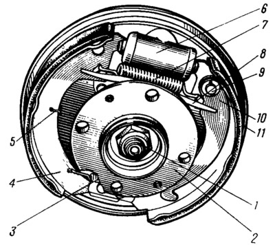
Pic. 85. Rear wheel brake:
1 - hub fastening nut; 2 - wheel hub; 3 - lower coupling spring of the shoes; 4 - brake shoe; 5 - guide spring; 6 - wheel cylinder; 7 - upper coupling spring; 8 - expanding bar; 9 - finger of the parking brake lever; 10 - lever for manual drive of the pads; 11 - shield of the brake mechanism.
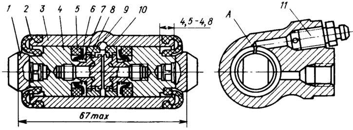
Pic. 86. Wheel cylinder:
1 - pad stop; 2 - protective cap; 3 - cylinder body; 4 - piston; 5 - sealant; 6 - support plate; 7 - spring; 8 - crackers; 9 thrust ring; 10 - persistent pint; 11 - fitting; A - a slot on the thrust ring.
The automatic clearance adjustment device is located in the wheel cylinder. Its main element is a split thrust ring 9 (see fig. 86), installed on the piston 4 between the shoulder of the thrust screw 10 and two crackers 8 with a gap of 1.25... 1.65 mm. Thrust rings are installed in the cylinder with an interference fit, providing a shear force of the ring along the cylinder mirror of at least 35 kgf, which exceeds the force on the piston from the coupling springs 3 and 7 (see fig. 85) brake pads. When the pads are worn, the gap of 1.25... 1.65 mm is completely eliminated, the collar on the stop screw is 10 (see fig. 86) is pressed against the shoulder of the ring 9, as a result of which the thrust ring is shifted after the piston by the amount of wear. With the cessation of braking, the pistons are shifted by the force of the coupling springs until the crackers stop against the collar of the thrust ring. Thus, the optimal clearance between the shoes and the drum is maintained.