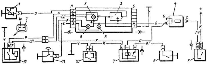
Pic. 166. The scheme of inclusion of control devices: 1 - coolant temperature indicator sensor; 2 - fuel level indicator with a reserve control lamp; 3 - coolant temperature gauge; 4 - fuse box; 5 - ignition switch; 6 — the switch of a control lamp of parking brake system; 7 - relay-breaker of the control lamp of the parking brake system; 8 - oil pressure control lamp; 9 — a control lamp of level of a brake liquid to parking brake system; 10 - brake fluid level sensor; 11 — the gauge of a control lamp of pressure of oil; 12 - sensor for level indicator and fuel reserve.
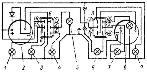
Pic. 167. Wiring diagram of the instrument cluster (view from the back): 1 — a control lamp of a driving beam of headlights; 2 - coolant temperature gauge; 3 — a control lamp of dimensional light; 4 — a control lamp of indexes to turn; 5 — a lamp of illumination of a combination of devices; 6 - control lamp of the battery discharge; 7 — a control lamp of pressure of oil; 8 - level indicator and fuel reserve; 9 - control lamp of the parking brake system and brake fluid level.
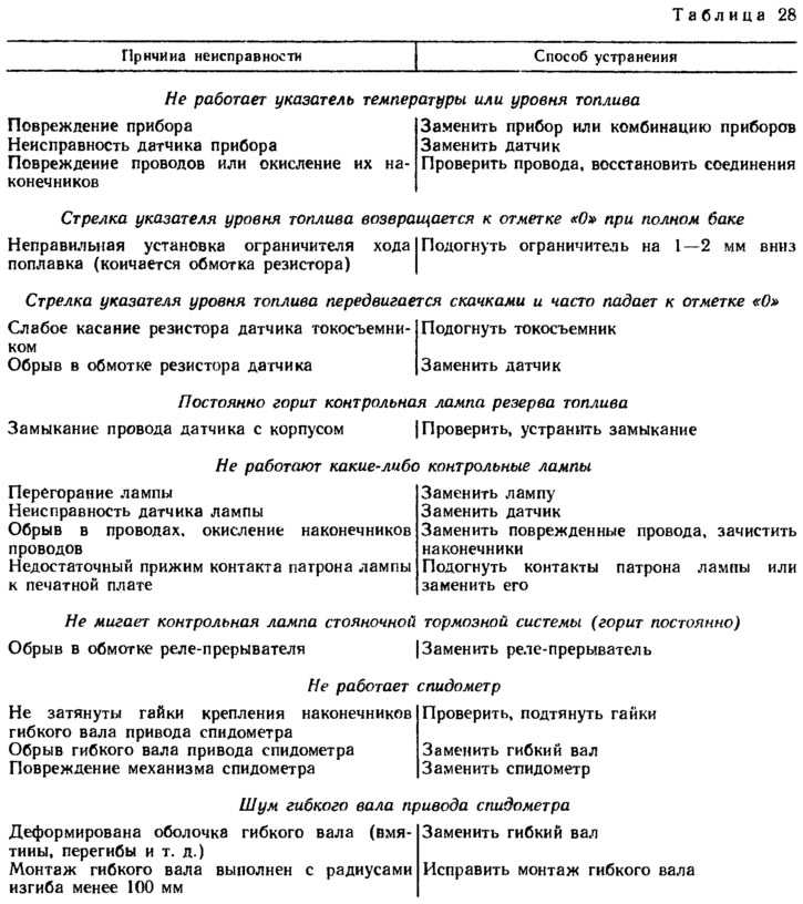
Possible malfunctions of devices, their causes and methods of elimination are given in Table. 28.