
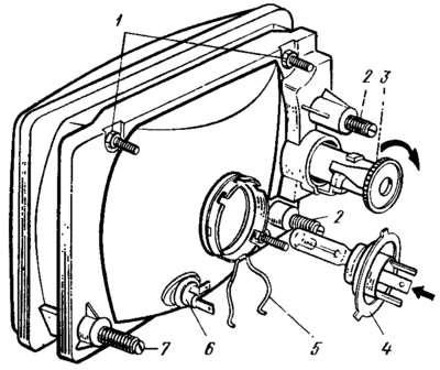
Pic. 161. Adjusting screws and headlight lamp: 1 - headlight mounting screws; 2 - screws for adjusting the beam of light in the vertical plane: 3 - adjusting screw; 4 - head light lamp; 5 - clamping latch; 6 — a lamp holder of a side light lamp; 7 - screw for adjusting the beam of light in the horizontal plane.
I install a fully fueled and equipped car with a load of 735 N on the driver's seat! on a flat horizontal platform 5 m from a smooth wall or any screen (shield measuring about 2X1 m) so that the axis of the car was perpendicular to it.
Before marking the screen, make sure that the air pressure in the tires is normal, and then rock the car from the side so that the suspension springs are installed.
Drawing on the screen (pic. 162) vertical lines: axial 0 and lines A and B passing through the points corresponding to the centers of the headlights. These lines must be symmetrical about the center line of the vehicle. At a height corresponding to the distance of the centers of the headlights from the floor, line 1 is drawn and below it by 65 mm line 2 of the centers of light spots. Turn set screws 3 (see fig. 161) to the far left.
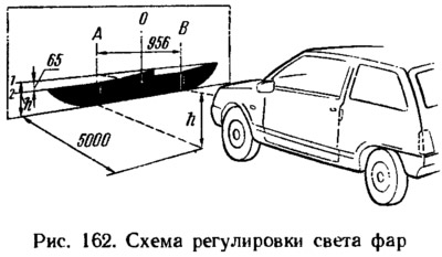
Turn on low beam headlights. Sequentially, first for the right headlight (the left is covered with a piece of cardboard or dark cloth or turned off), and then for the left (right closed) adjust with screws 2 and 7 the light beams of the headlights. For correctly adjusted headlights, the upper border of the light spots must coincide with line 2 (see fig. 162), and the points of intersection of the horizontal and inclined sections of light spots - with points E.
Three lever switch
The switch is mounted with a clamp on the steering shaft bracket. To remove a damaged switch, remove the steering wheel, and then the two halves of the steering shaft cover. Remove the instrument cluster and disconnect the switch wires from the vehicle wiring harness.
Loosen the clamp and remove the switch.
Relay-interrupter for direction indicators and alarms
Relay-breaker 8 (see fig. 160) is designed to receive an intermittent light signal of direction indicators both in the alarm mode and in the direction indication mode, as well as to check the serviceability of the direction indicator lamps. If the lamps are in good condition, then in the turn indication mode, the relay-breaker creates a flashing of the control lamp 7.
If the lamps are faulty (burnout or open circuit in the lamp circuit), then the relay-breaker provides a flashing of the control lamp with a double frequency. The relay-breaker is installed under the instrument panel on the left side. A defective breaker relay cannot be repaired and must be replaced with a new one. The relay-interrupter must ensure the flashing of the direction indicator lamps at a frequency of 90±30 cycles per minute at a rated load of 92 W, an ambient temperature of -40 to +55°C and a supply voltage of 10.8 to 15 V.
Relay for turning on headlights and other consumers
To turn on the headlights, relays of type 113.3747-10 are used, installed under the instrument panel on the left side, together with other relays and fuses. The same relays are also used to turn on the starter, rear window heating and the engine cooling fan motor, as well as to turn on the ignition. Relay switch-on voltage at temperature (23±5) °C is 8 V, and the winding resistance (85±8,5) Ohm.