
Headlights
The scheme of inclusion of headlights is shown in fig. 158. The dipped and main beam headlights are switched on using auxiliary relays 3 and 11. The control voltage to the relay windings is supplied from the headlight switch 10 (switch lever is located to the left of the steering column), if the key of the switch 8 of the outdoor lighting is fully pressed.
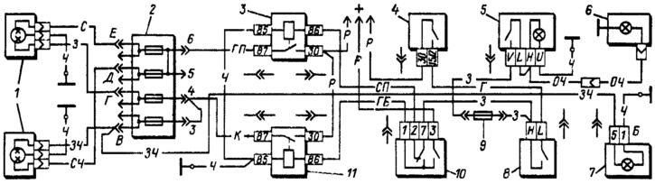
Pic. 158. Scheme of inclusion of headlights and fog lamp: 1 - headlights; 2 - fuse block; 3 — the relay of inclusion of a passing beam of headlights; 4 - ignition switch; 5 - fog light switch; 6 - rear fog light; 7 — a control lamp of inclusion of a high beam; 8 - outdoor lighting switch; 9 - fog light circuit fuse: 10 - headlight switch; 11 - high beam headlight relay.
Regardless of the position of the switch keys 8, you can briefly turn on the high beam of the headlights by pulling the headlight switch lever 10 towards you, i.e., carry out a light signaling. In this case, the voltage to the light signaling contact of switch 10 is supplied directly from the power sources, bypassing the ignition switch.
Outdoor Lighting
The switching circuit is shown in fig. 159. The side light in the headlights and taillights is switched on by the switch 3 for outdoor lighting. At the same time, the lamps of the license plate lights 6, the instrument cluster lighting lamp 5 and the indicator lamp 4 for turning on the side light also light up.
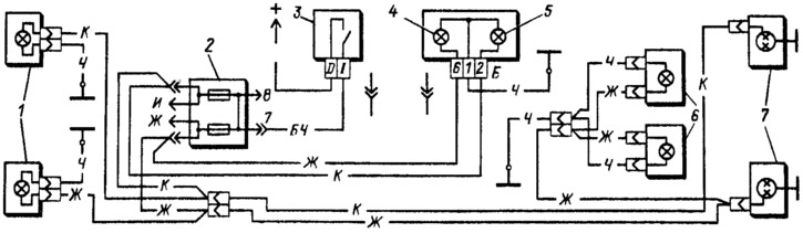
Pic. 159. Scheme for switching on outdoor lighting: 1 - side light lamps in the headlights; 2 - fuse box; 3 - outdoor lighting switch; 4 — a control lamp of dimensional light; 5 — a lamp of illumination of a combination of devices; 6 - license plate lights; 7 - side light lamps in the rear lights.
Direction indicators and alarms
The switching circuit is shown in fig. 160. Turn indicators of the right or left side are switched on by the switch lever 4 (to the left of the steering column). In alarm mode, switch 3 (located on the instrument panel) all direction indicators and the control lamp in the switch 3 are turned on. The flashing of the lamps is provided by the relay-breaker 8.
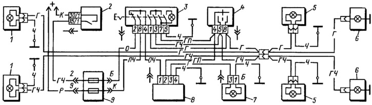
Pic. 160. The scheme of inclusion of direction indicators and alarms: 1 - front direction indicators; 2 - ignition switch; 3 - alarm switch; 4 - turn signal switch; 5 - side direction indicators; 6 - direction indicator lamps in the rear lights; 7 — a control lamp of indexes of turn; 8 - relay-breaker of direction indicators and alarm; 9 - fuse block.
Sound signal
The car is equipped with a sound signal type C-304 or C-305. It is located in the engine compartment and is mounted on a bracket to the radiator frame panel. If the signal strength decreases or wheezing appears, adjust the signal by turning the screw on its body in one direction or another until a loud and clear sound is obtained.
If the adjustment does not eliminate wheezing or the signal is intermittent, then the signal is disassembled and the breaker contacts are cleaned. When assembling the signal, the old gasket is installed between the membrane and the signal housing so as not to disturb the gap between the core and the armature.
If the signal does not turn on, then check the reliability of the wire connection, in particular the wire connecting the steering gear to the body, and check the condition of the switch contacts. Clean contacts if necessary.