
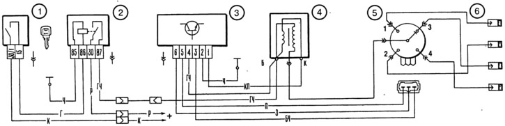
Pic. 7-17. Ignition system diagram:
1 - ignition switch; 2 - ignition relay; 3 - switch; 4 - ignition coil; 5-sensor-distributor ignition; 6 - spark plugs.
Ignition distributor - type 3810.3706, four-spark, unshielded, with vacuum and centrifugal ignition timing controllers, with built-in microelectronic control impulse sensor.
Switch - type 3620.3734, or 76.3734, or RT1903, or PZE4022, or K563.3747. It converts the control pulses of the sensor into current pulses in the primary winding of the ignition coil.
Ignition coil - type 8352.12, or 27.3705, or 027.3705, or 27.3705-01 - oil-filled, sealed with an open magnetic circuit.
Spark plugs - type A17DVRM or A17DVRM1 with noise suppression resistors.
Ignition switch - type 2101-3704000-11 with anti-theft locking device.
Warnings
The vehicle adopts a high energy ignition system with a wide application of electronics. Therefore, in order not to get injured and not to disable the electronic components, the following rules must be observed.
Do not touch ignition system components while the engine is running (switch, ignition coil and high voltage wires).
Do not start the engine using the spark gap and do not check the operation of the ignition system «for a spark» between the spark plug wire ends and «weight».
Do not run the low voltage wires of the ignition system in the same bundle as the high voltage wires.
Ensure the connection is secure with «weight» switch through the mounting screws. This affects its smooth operation.
With the ignition on, do not disconnect the wires from the battery terminals and do not disconnect the plug connector from the switch, as this may cause increased voltage on individual elements of its circuit and it will be damaged.