If the engine does not start or runs intermittently, it is recommended to start checking the ignition system from the high-voltage part in the following order.
Checking the high voltage part
To check, you need a simple spark gap (pic. 118) with two pairs of metal rods 2 and 5 (electrodes), fixed on a plate of insulating material (plastic, textolite). The lower part of the rods, together with insulators 7, must correspond in shape and size to the dimensions of the insulator and the tip of the spark plugs. Screws 6 with pointed ends are wrapped in the upper part of the rods. The gap between the ends of the screws can be adjusted by turning the screws.
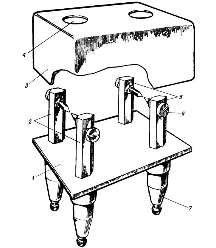
Pic. 118. Arrester for checking the high-voltage part:
1 - insulating base; 2 - electrodes connected to the wires of the spark plugs of the 1st and 4th cylinders; 3 - casing; 4 - viewing window; 5 - electrodes connected to the wires of the spark plugs of the 2nd and 3rd cylinders; 6 - adjusting screws; 7 - insulating sleeves.
Care must be taken when checking the high voltage part. For this purpose, the arrester must be covered from above with a cover 3 made of insulating material with viewing windows 4. The arrester must be mounted on the car body.
Disconnect the wire ends from the spark plugs and attach them to the arrester electrodes. Connect the wires from the candles of the 1st and 4th cylinders to one pair of electrodes, and from the candles of the 2nd and 3rd - to another pair of electrodes. Set the gap between the spark gap electrodes to 7...10 mm and turn the engine over with the starter.
At a low crankshaft speed, an alternate spark jump between the pairs of electrodes 2 and 5 will be noticeable. If the sparking on the arrester is normal, then all spark plugs must be checked.
If there is no sparking on one pair of electrodes, then it is necessary to check the electrical circuit from the switch to these electrodes: high-voltage wires, interference suppression tips, ignition coil and connection of the coil to the switch.
When there is no sparking on both beds of the arrester electrodes, then you should check whether power is supplied to the switch, controller and ignition coils, and also check the switch, controller and NO and UI sensors if the power circuits are OK.
Switch
The simplest switch test can be done with an A12, 3 W lamp. To do this, disconnect the low-voltage wires from the ignition coil, attach a lamp to them and crank the engine with a starter. A blinking lamp will indicate that the switch is generating current pulses.
If there are no current pulses on only one ignition coil, then either the wires connecting this ignition coil to the switch are damaged, or one of the switch channels is faulty.
If there are no current pulses on both coils, then either the supply voltage is not supplied to the ignition coils, switch or controller (blue wire with red stripe), or the malfunction must be looked for further. Perhaps it is in the switch, the controller, or in the connections between them.
If you have a known-good switch, you can replace the car's switch with it and check the operation of the ignition system. Its normal operation in this case will indicate that the car had a faulty switch.
Controller
The simplest check of the controller's performance can be performed using the indicator assembled according to the diagram in Fig. 119. The indicator uses resistors of the MLT type, 1 W, a transistor of the KT817B type, and an A12 automotive lamp, 3 W as an indicator lamp L1.
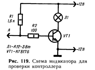
To test the controller, you need to connect the leads «—» and «+» indicator with battery, disconnect the plug connector from the switch and connect the input «A» indicator to plug «5» this block (connected with white wire). Turn the engine over with the starter. If the indicator lamp flashes, the controller issues a pulse «Channel selection».
Similarly, the presence of impulses is checked «Ignition signal» connecting the indicator input to the plug «6» (blue wire goes to it) wiring harness disconnected from the switch.
If there are no pulses, then you should check whether the power supply is supplied to the controller and whether there is a break in the wires connecting the controller to the switch and to the NO and UI sensors. If the wires are intact and the supply voltage is supplied to the controller, but there are no pulses, then it is necessary to check the controller on the stand at the service station.
To test the control function of the carburetor solenoid valve, disconnect the green wire from the limit switch 8 (see fig. 112) carburetor and connect the tip of this wire to «weight». Then start the engine and gradually increase the crankshaft speed. At 1750 rpm (measured by some additional tachometer) valve should turn off. Now slowly reduce the speed. When it drops to 1650 rpm, the valve should turn on.
Set the speed to 2000 rpm, disconnect from «masses» tip of the wire going to the carburetor limit switch, and then reconnect it to «weight». When disconnecting the wire from «masses» the valve must turn on, and when connected to «weight» - turn off. The moment of valve operation can be determined by a characteristic click or using a voltmeter connected to the valve and «mass». If the valve is on, then the voltmeter should show a voltage of at least 10 V, and if it is off, then no more than 1.5 V.
Ignition coil
At the ignition coil, it is checked if there is an open in the winding or a short circuit between the windings, and also if there is an insulation breakdown on «mass», which is detected by burnout or melting of the plastic shell of the coil on its side adjacent to the mounting bracket.
Synchronization sensors
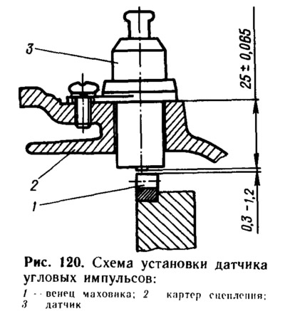
Roughly assess the presence of pulses generated by the sensor, you can use an AC voltmeter, cranking the engine with a starter. If there are no pulses, then it is necessary to check if there is a break in the sensor winding and the correct installation of the sensor. For normal operation of the sensor, it is necessary that the gap between the sensor and the top of the flywheel ring tooth (or the end face of the pin for the NO sensor) was within 0.3... 1.2 mm (pic. 120).
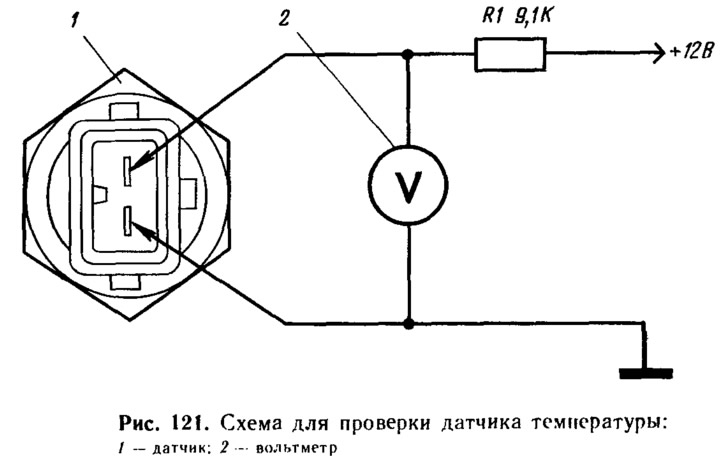
Temperature sensor
To check, place the sensor in a tank of water and attach a power source and a voltmeter to it (pic. 121). Turning on the water heating, measure the voltage drop across the sensor at different temperatures in the tank. The voltage drop should not differ by more than±0.1 V from the calculated one, determined by the formula: U = 10 TK [mV].
Here TK is the temperature of the water in the tank, expressed in K.