




Contents: Spark plug ↓ Ignition coil ↓ Ignition switch ↓ Distributor ↓ High voltage wires ↓ Operation of the ignition system ↓
The ignition system components include: spark plug, ignition coil, ignition switch, ignition distributor, and high and low voltage wires.
Open large image in new tab »
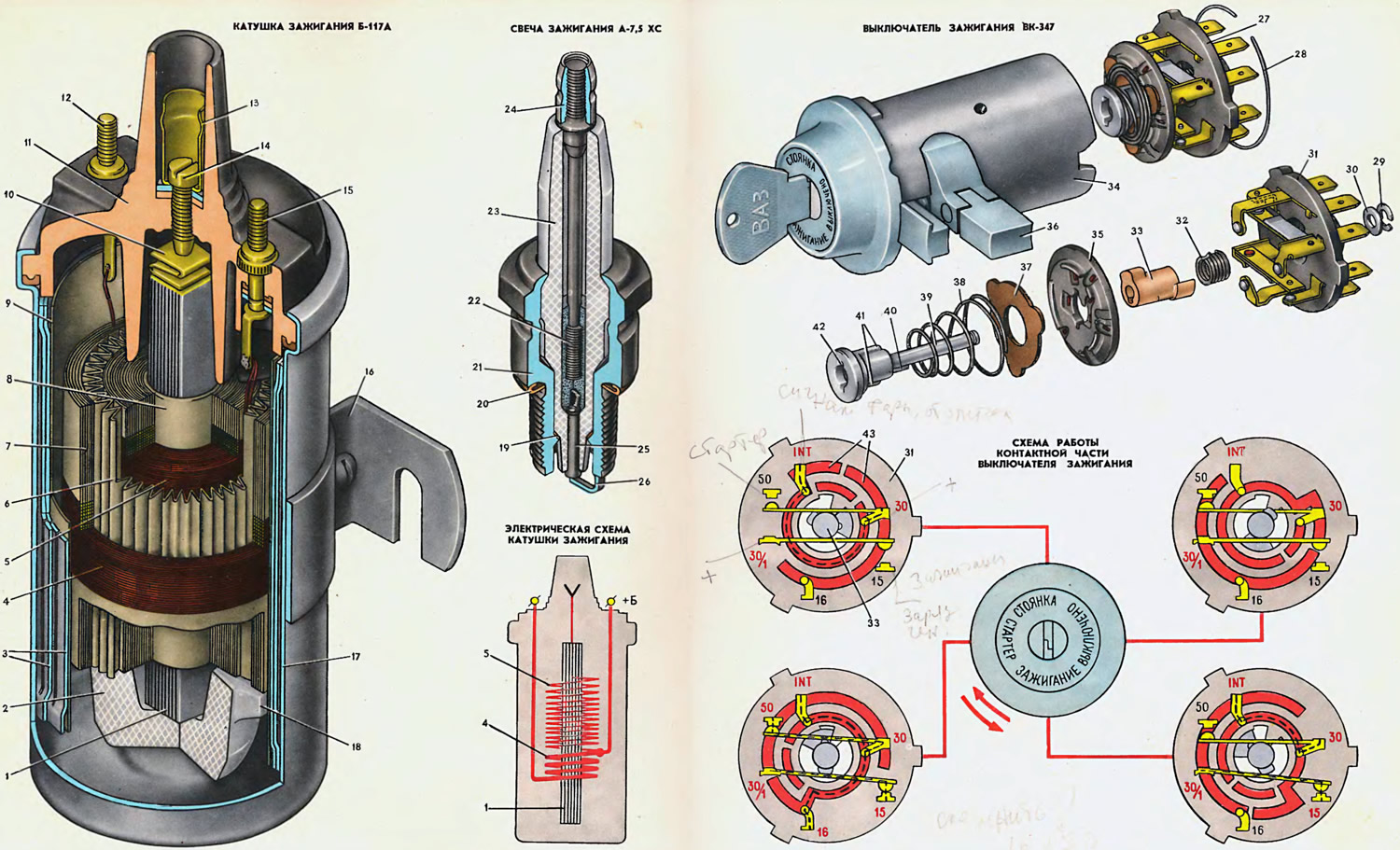
1. Core. 2. Insulator. 3. Outer magnetic circuit. 4. Primary winding. 5. Secondary winding. 6. Corrugated cardboard layer. 7. Winding insulating paper. 8. Secondary winding frame. 9. Outer insulation of the primary winding. 10. Spring. 11. Cover. 12. Primary winding end terminal. 13. High voltage terminal (secondary winding start terminal). 14. Contact screw. 15. Terminal "+B" of the output of the beginning of the primary winding and the end of the secondary. 16. Coil mounting bracket. 17. Housing. 18. Insulator rib. 19. Heat-sink washer. 20. Sealing ring. 21. Housing. 22. Rod. 23. Insulator. 24. Contact nut. 25. Central electrode. 26. Side electrode. 27. Contact part. 28. Spring ring. 29. Lock washer. 30. Washer. 31. Block. 32. Spring. 33. Cylinder. 34. Housing. 35. Rotor. 36. Locking rod of the anti-theft device. 37. Textolite washer. 38. Spring. 39. Roller. 40. Protrusion for connection with cylinder 41. Protrusion for connection with rotor 35. 42. Groove for connection with drive sleeve of anti-theft device. 43. Slip rings of rotor 35.
Spark plug
The spark plug is designed to ignite the combustible mixture in the engine cylinders by a spark discharge between the electrodes.
Since 1973, Zhiguli cars have been using A-7.5 HS spark plugs. Previously, A-7.5 BS spark plugs were used. They differ only in the insulator material. The letter A in the spark plug designation indicates that the thread of the screw-in part is M14X1.25, and these spark plugs have a thread made according to the ISO standard with a precision class of 6e. The numbers 7.5 are the length of the thermal cone (skirt) of the insulator. The second letter in the designation indicates the insulator material: B - borocorundum, X - hilumin. The last letter C means that the spark plug is sealed along the central electrode with a conductive material.
The spark plugs are non-separable. The steel body 21 has a threaded section 19 mm long and a hexagonal section with a spanner size of 20.8 mm. A side electrode 26 made of nickel-manganese wire is welded to the body. The insulator 23 is made of high-quality ceramic material with very high mechanical and electrical strength at high temperatures. The outer surface of the insulator is glazed to improve the insulating properties and reduce moisture deposits, thereby reducing the possibility of surface discharge when high voltage is applied to the spark plug. In the insulator opening there is a composite central electrode consisting of the electrode 25 itself, made of heat-resistant chromium-nickel alloy, and a steel rod 22. On the upper part of the rod there is a thread on which a contact nut 24 is screwed to attach the tip of the high-voltage wire. Rod 22 is filled in the insulator with conductive glass sealant, preventing gas breakthrough through the insulator hole. The gap between the spark plug body and the insulator is sealed by crimping the body around the insulator flange, as well as by copper washer 19, which simultaneously serves to remove heat from the insulator to the body, maintaining the temperature of the insulator skirt at a certain level
This temperature depends on the length of the skirt and the thermal stress of the engine. The longer the skirt, the worse the heat dissipation from the skirt to the body, the "hotter" the spark plug. For each engine model, the spark plug is selected individually, since the insulator skirt must heat up to a temperature of 500-600°C. If the temperature is below 500°C, i.e. the skirt is short and the spark plug is "cold", then carbon deposits will be intensively deposited on the insulator skirt. If the temperature is above 600°C, the carbon deposits will burn off, but the engine will experience premature ignition of the combustible mixture from the heated skirt, and not from the spark. This phenomenon is called pre-ignition and is manifested by knocking in the engine and the fact that after the ignition is turned off, the engine continues to run for some time.
The approximate thermal properties of the spark plug are determined by the length of the insulator skirt, which is indicated in the spark plug marking.
A sealing ring 20 made of soft iron, which is clamped between its body and the surface of the socket in the cylinder head, serves to prevent gas leakage through the spark plug body thread.
Ignition coil
The Zhiguli cars are equipped with an ignition coil of the B-117A type of domestic production or B-117 produced by the NRB. The characteristics of these coils are the same, and the differences are only in small design elements. The coil is located in the engine compartment and is attached with two bolts welded to the lower part of the left wheel mudguard.
The ignition coil is used to convert intermittent low-voltage current (12 V) into high-voltage current (11-20 kV) to break down the air gap between the spark plug electrodes. The coil is a transformer on an "iron" core 1 and an annular external magnetic circuit 3. The core is made of 0.5 mm thick electrical steel plates, and the external magnetic circuit consists of a 0.3 mm thick electrical steel tape folded into two layers. The tape has vertical slits to reduce eddy currents.
The core 1 is located in a cardboard frame 8, on which the secondary winding 5 is wound. The primary winding 4 is wound on top of the secondary. The winding layers are separated from each other by layers of insulating paper, and the first layer is separated from the others by a layer of corrugated cardboard. The primary winding is insulated from the secondary by insulating paper and plastic tape, and from the magnetic circuit 3 by a layer of electrically insulating cardboard.
The windings together with the magnetic circuit and the core are placed in a solid-drawn aluminum case 17 and filled with transformer oil. Filling with oil increases the reliability of the insulation and improves the cooling of the windings. The windings are installed in the case on a cup-shaped insulator 2 made of a ceramic material - steatite.
The coil body is closed from above with a plastic cover 11, the flange of which is rolled into the body and sealed with a gasket made of oil-resistant rubber. The winding terminals are connected to the terminals cast into the cover. The terminals of the beginning of the primary and the end of the secondary winding are soldered to terminal 15, marked "+B", and the terminals of the beginning of the primary and the end of the secondary winding are soldered to terminal 12 (without marking) soldered terminal of the end of the primary winding. Terminal of the beginning of the secondary winding (high voltage terminal) connected to the core plates and then, through spring 10 and screw 14, to terminal 13, to which the high-voltage wire is connected.
Ignition switch
On VAZ-2101 and VAZ-2102 cars, ignition switches of the VK-333 type without an anti-theft device or ignition switches of the VK-347 type with an anti-theft device and a contact part are installed. On the VAZ-2103 car, only the VK-347 ignition switch is installed, which is described here. The operating principle and characteristics of the VK-333 switch are basically the same as those of the VK-347 switch.
The ignition switch is designed to turn on and off the ignition circuits, instruments, lights and other consumers of electrical energy in the car. It is mounted on a bracket on the left side of the steering column and secured with two screws.
The switch consists of a housing 34 with a lock and an anti-theft device and a contact part 27 secured in the housing by a spring ring 28. The principle of operation of the anti-theft device is that after removing the key from the lock set to the PARKING position, the locking rod 36 extends, enters the groove of the steering shaft and locks the shaft. In this case, the steering wheel must be turned right and left so that the shaft groove is opposite the locking rod of the lock. The switch lock is designed so that the key can only be removed in the PARKING and OFF positions.
The contact part has a steel roller 39, onto which a plastic rotor 35 with contact rings 43 and a plastic cylinder 33 with projections are placed. In the head of the roller there is a groove 42, into which the projection of the leading sleeve of the anti-theft device enters. One side of the groove has a width of 2.5 mm, and the other is 2 mm. Therefore, the contact part 27 can be installed in the housing 34 only in one specific position. Spring 32 serves to return the roller 39 from the STARTER position to the IGNITION position after releasing the key.
Brass posts-plugs with contacts are installed in block 31. Bronze plates with contacts are fixed on posts-plugs "30" and "30/1". The plates are pressed to the surface of cylinder 33 by plate springs. In the IGNITION and STARTER positions, the projections of cylinder 33 press these plates and contacts "30-50" and "15-30/1" close. In addition, posts "30", "INT" and "16" have contacts that are closed by contact rings 43 of rotor 35. The rotor is pressed against these contacts by spring 38.
Voltage from the battery and generator is supplied to contacts "30" and "30/1". Contact "16" of the switch is not used yet. The diagram shows which contacts are closed in different positions of the key.
Distributor
Open large image in new tab »
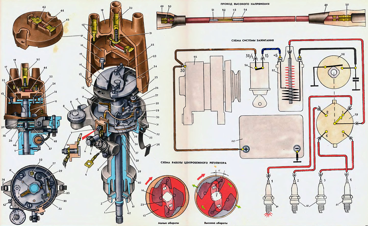
1. Ignition distributor shaft. 2. Oil-reflecting ring. 3. The capacitor. 4. Wire from the ignition coil to the distributor. 5. Spring clip of the lubrication channel of the oil pan. 6. Oil pan body. 7. The terminal block screw. 8. The eccentric of the octane corrector. 9. The eccentric axis. 10. Eccentric spring. 11. Breaker cam. 12. Cam oil wick (field). 13. Base plate of the ignition timing regulator. 14. The weight of the ignition timing regulator. 15. Weight stop. 16. Rotor mounting screw. 17. Ignition distributor rotor. 18. Side electrode with a terminal for the wire to the spark plug. 19. Ignition distributor cap. 20. Central terminal for the wire from the ignition coil. 21. Central carbon electrode with spring. 22. Spring mounting post with limiter. 23. Leading plate of the ignition timing regulator. 24. The weight axis. 25. Chopper lever axis. 26. Insulation sleeve. 27. Lever spring. 28. Textolite lever block. 29. Breaker lever. 30. Movable contact of the interrupter. I. Connecting conductor of the interrupter. 12. Fixed contact of the interrupter. 13. Rack mount screw. 14. Cover mounting spring. 15. Fixed breaker plate. 16. Rack with interrupter contacts. 17. Movable breaker plate. 18. Base plate. 19. Metal-ceramic porous roller sleeve. 10. Ignition distributor housing. 11. Washer of the oil-reflecting ring. 42. Spiral hairpin. 43. Central contact of the rotor 44. The resistor. 45. External contact of the rotor. 46. Octane corrector thrust axis. 47. Thrust of the octane corrector. 48. Grease wick (filz) of the roller sleeve. 49. Rubber cover. 50. Wire tip. 51. Conductive winding. 52. Inner shell. 53. Flax fiber core. 54. Outer insulating shell. 55. Generator. 56. Ignition switch. 57. Ignition coil. 58. Ignition distributor interrupter. 59. Ignition distributor. 60. Rechargeable battery. 61. Spark plugs.
The ignition distributor serves to interrupt the current in the low voltage circuit of the ignition coil and distribute high voltage pulses to the spark plugs.
The Zhiguli cars use a four-spark, unshielded ignition distributor of the R-125 type (R-125B for VAZ-2103) with centrifugal ignition timing regulator and octane corrector.
The R-125 and R-125B ignition distributors differ in the characteristics of the ignition advance regulator and the length of the lower part of the shaft 1 protruding from the housing 40: for the R-125 distributor, the size from the support flange of the housing to the end of the shaft is 127.5 mm, and for the R-125B distributor - 136.3 mm.
The distributor housing 40 is cast from an aluminum alloy and has a porous metal-ceramic bushing 39, in which the shaft 1 rotates. Lubricant is supplied to the bushing through a felt wick (felt) 47 from the oiler 6.
The main parts of the ignition distributor are: the breaker, the centrifugal ignition timing regulator and the distributor itself.
The interrupter consists of a cam 11 with four projections and a post 36 with contacts that the cam opens when rotating. The cam is lubricated with a felt pad 12 soaked in oil. An axis 25 is riveted to the post 36, on which a lever 29 with a contact 30 is mounted on a textolite bushing 26, pressed by a leaf spring 27 to the contact 32 of the post. Current is supplied to the contact of the lever from a screw 7 through a conductor 31 and a spring 27.
The stand 36 is secured with two screws 33 on the movable plate 37 of the interrupter. The lower end of the axis 25 of the lever enters the hole of the movable plate. Therefore, when adjusting the gap between the contacts, the stand can be rotated around this axis after loosening the screws 33.
The movable plate 37 of the breaker is soldered to the bushing through which the distributor shaft passes. A plastic support plate 38 and a fixed plate 35 of the breaker are put on this bushing. These plates are compressed by a spring washer and secured to the bushing by a locking ring. The movable plate 37 of the breaker with the stand 36 can be turned by the rod 47 of the octane corrector, which allows the ignition advance angle to be adjusted manually within small limits.
Cam 11 is driven into rotation not directly by the distributor shaft, but through weights and can be rotated by them by 15° relative to the distributor shaft.
The support plate 13 of the ignition advance regulator is soldered to the upper end of the cam bushing. Axles 24 are riveted to the plate, on which metal-ceramic weights rotate. The spring posts 22 are pressed into the plate 23. The lower parts of the axes are limiters. They enter the oval grooves of the plate 13 and do not allow it to rotate relative to the distributor shaft by more than 15°.
The distributor consists of a rotor 17 and electrodes installed in a plastic cover 19. The plastic rotor 17 is secured with two screws 16 on the plate 13 of the ignition advance regulator. The rotor is secured in a certain position, which is ensured by square and round holes in the plate 13, into which the rotor projections of the same cross-section enter. The central 43 and outer 45 rotor contacts are riveted to the rotor, between which in a special recess there is a resistor 44 of 5000-6000 Ohm, designed to suppress radio interference.
The spring-loaded carbon electrode 21 rests against the central contact of the rotor, transmitting high-voltage pulses from the ignition coil to the rotor. When the rotor rotates, these pulses are transmitted from the outer contact 45 to the side electrodes 18, filled into the cover, and then to the spark plugs.
A capacitor 3 with a capacity of 0.20–0.25 μF is attached to the ignition distributor housing.
High voltage wires
High-voltage wires are used to transmit high-voltage current pulses from the ignition coil to the distributor and from the distributor to the spark plugs. To reduce radio and television interference, the wires have a resistance distributed along their length of 2000 Ohm/m. The core 53 of the wire, which is a cord made of flax yarn, is enclosed in a shell 52 made of plastic with a maximum addition of ferrite. A wire ∅ 0.11 mm made of nickel-iron alloy is wound over this shell.
Operation of the ignition system
The ignition system has a primary circuit (low voltage) and secondary (high voltage). The current in the primary circuit is closed along the path: "plus" of the battery - contacts "30/1", "15" ignition switch - terminal "+B",
primary winding of the coil — breaker 58 — ground — "minus" of the storage battery. If the generator voltage is greater than the battery voltage, the current goes from the "30" terminal of the generator and closes through the ground to its rectifier. Otherwise, the current path is the same as described above.
The current flowing through the primary winding of the ignition coil creates a magnetic field around the turns. When the breaker contacts open, the current in the primary circuit disappears, the magnetic field is sharply reduced and, crossing the turns of the primary and secondary windings, induces an EMF in them proportional to the number of turns. In the secondary winding, the EMF reaches 12,000-24,000 V, and in the primary - 200-300 V. The faster the magnetic lines of force cross the turns of the windings (i.e. the magnetic field disappears faster), the greater the EMF induced in them.
The EMF induced in the primary winding of the ignition coil is called the self-induction EMF. It tends to support the disappearing current and, therefore, slow down the reduction of the magnetic field. In addition, it causes sparking between the open contacts of the breaker. In order to prevent these phenomena, there is a capacitor 3 in the ignition distributor. At the initial moment of opening the contacts, the self-induction current charges the capacitor, which reduces the flow of current between the contacts of the breaker and sparking between them. Then the capacitor is discharged through the primary winding of the ignition coil, and the discharge current is directed against the self-induction current, due to which the disappearance of the current in the primary circuit occurs faster and, therefore, the magnetic field is reduced faster.
The high-voltage current induced in the secondary winding of the ignition coil is closed along the following path: secondary winding of the ignition coil - high-voltage wire - central terminal of the cover, central contact 43, resistor 44, outer contact 45 of the rotor, side electrode of the distributor cover - spark plug - ground. Then, along parallel circuits, the current passes through the battery, through the generator, through all the included consumers to contacts "30/1" and "15" of the ignition switch, and then to the "+B" terminal to the secondary winding of the ignition coil.
High voltage supplied to the central electrode of the spark plug breaks the air gap between the electrodes and a spark jumps between them, igniting the working mixture in the engine cylinder.
To obtain maximum power and efficiency of the engine, it is necessary to ignite the working mixture a little earlier than the piston reaches TDC, so that combustion ends when the crankshaft crank turns 10-15° after TDC, i.e. the spark discharge must be created with the required lead time.
Each engine speed requires its own ignition advance angle. When the crankshaft speed decreases, the ignition advance angle should decrease, and when the speed increases, it should increase. This work is performed by a centrifugal ignition advance regulator. When the distributor shaft speed increases, the weights 14 rotate relative to the axes under the action of centrifugal force. The projections of the weights rest against the leading plate 23 and, overcoming the tension of the springs, rotate the support plate 13 together with the breaker cam 11 in the direction of rotation of the distributor shaft by an angle of a. The cam projections open the breaker contacts earlier and the ignition advance increases. When the shaft speed decreases, the centrifugal forces acting on the weights decrease and the springs rotate the support plate 13 with the cam 11 against the direction of rotation of the shaft, i.e. the ignition advance decreases.
The text is copied from the online portal (vazbook)