
The liners are installed in the sockets and caps of the main bearings, the crankshaft assembly with the balance shaft drive gear is placed in the main bearings, and thrust semi-rings are inserted into the sockets of the middle main bearing with grooves towards the thrust surfaces of the crankshaft (on the side of the grooves, an anti-friction layer is applied to the surface of the half-rings).
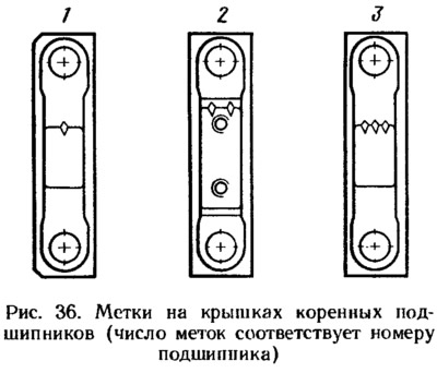
Install the main bearing caps in accordance with the marks that are applied to their outer surface (pic. 36). The covers must be positioned so that the marks are on the generator mounting side. Tighten the cover bolts.
Check the axial play of the crankshaft. To do this, turn the block with its back side up and install a stand with an indicator on it so that the indicator leg rests against the crankshaft flange. Moving the shaft with screwdrivers as levers up and down, measure the axial play with an indicator. It should be in the range of 0.06-0.26 mm. If the backlash is greater, then they bring it back to normal by replacing the old half-rings with new ones or by installing half-rings with a thickness increased by 0.127 mm.
The gears are mounted on the balancing shafts in such a position that the alignment marks on the gears are against the marks on the crankshaft drive gear (see fig. 25). Install the washers and fix the gears with bolts.
Installed in holder 3 (pic. 37) rear oil seal 1 of the crankshaft, having previously lubricated it with engine oil. The displacement of the stuffing box inward relative to the outer surface B of the holder should be no more than 0.25 mm. Protrusion of the stuffing box relative to surface B is not allowed. Press two mounting bushings 2 into the holder of the rear oil seal, ensuring that the bushings protrude (6,5±0,2) mm on the side opposite the cylinder block.
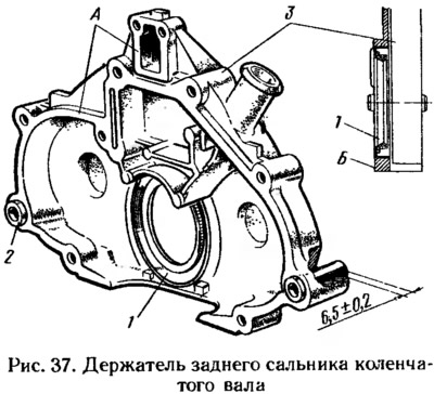
They clean the mating surfaces of the holder and the cylinder block from the remnants of the old sealant, dirt, oil and degrease. On surfaces A of the holder, mating with the cylinder block, KLT-75T sealant is applied in a continuous strip with a width of at least 3 mm. Put the holder with the stuffing box on the conical mandrel 41.7853.4011 (see fig. 23) and move it from the mandrel to the crankshaft flange. Attach the holder to the cylinder block with bolts and nuts.
Install the flywheel on the crankshaft along the mounting sleeve so that the mark (cone-shaped hole) near the rim was against the axes of the connecting rod journals of the crankshaft. Install the washer and flywheel mounting bolts. Block the flywheel with a latch (see fig. 35) and tighten the mounting bolts.
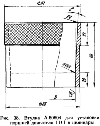
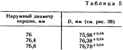
Assemble pistons with connecting rods (see sect. «Connecting rod and piston group»). With bushing A.60604 (pic. 38) for engines 11111, compressing the piston rings, pistons with connecting rods are inserted into the cylinders. Inner diameter (tab. 5) sleeve is selected in accordance with the diameter of the installed piston. To install the pistons of the engine 11113, a split adjustable sleeve 67.7854.9519 is used.
Pistons have an arrow (see fig. 5) towards the camshaft drive.
Install the bearings in the connecting rods and connecting rod caps. Connect the connecting rods to the crankshaft journals, install the covers and tighten the connecting rod bolts. Connecting rod caps must be installed so that the cylinder number on the cap is opposite the cylinder number on the bottom end of the connecting rod.
Using mandrel 67.7853.9580, press the crankshaft front oil seal into the oil pump cover. Pour a little engine oil into the oil pump and turn the drive gear several times, stopping in such a position that it can be put on the front end of the crankshaft. Insert the guide sleeve of mandrel 67.7853.9580 into the stuffing box pressed into the oil pump and move the pump from the guide sleeve onto the shaft. Install a gasket under the pump and attach it to the cylinder block.
For proper installation of the pump, two guide pins are pressed into its housing, which must fit into the corresponding holes in the cylinder block.
Insert an oil receiver with an o-ring into the hole of the oil pump, attach it to the oil pump and to the cover of the middle main bearing of the crankshaft (see fig. 34).
Install the oil sump with gasket and secure it. Install on the cylinder block and bolt the oil filter flange with gasket. Wrap the sensor of the oil pressure warning lamp in the flange. Lubricate the oil filter o-ring with engine oil and screw the oil filter to the flange fitting by hand.
Insert two centering bushes into the cylinder block (pic. 39) and install a new cylinder head gasket on them; A used gasket must not be used.
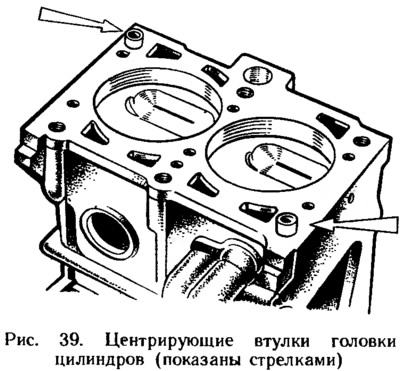
Before installing the gasket, remove oil from the mating surfaces of the block and cylinder head. The gasket must be clean and dry. If oil gets on the surface of the gasket, degrease it.
Turn the crankshaft so that the pistons are in the middle part of the cylinders, and install the cylinder head assembled in accordance with the instructions in subsection «cylinder head» (see sect. «Dismantling and assembly of engine components») .
Check the length of the cylinder head bolts (without bolt head). If the length of the bolts is more than 135.5 mm, then replace them with new ones. In advance, before assembling the engine, lubricate the threads and bolt heads by dipping them in engine oil, and then allow the excess oil to drain. In addition, it is necessary to remove oil from the bolt holes in the cylinder block (if it got there), otherwise, when tightening the bolts, cracks may appear in the cylinder block.
The cylinder head bolts are tightened in sequence to ensure a good seal and to prevent bolt re-tightening during maintenance (see fig. 21) and in four doses (see sect. «cylinder head») .
The coolant pump with gasket is inserted into the socket of the cylinder block, checking the reliability of pressing the pump pulley onto the roller (see sect. «coolant pump»). Install the rear toothed belt cover and attach it together with the pump cover to the cylinder block. Additionally, attach the cover with a bolt to the cylinder block and a nut to the stud on the cylinder head.
Segmented keys are inserted into the sockets at the front ends of the crankshaft and camshaft and toothed pulleys are installed. Holding the pulley from turning with tool 67.7811.9513, fix the pulley with a bolt with a washer. Before installation, a sealant of the UG-6 type is applied to the bolt thread.
Turn the camshaft pulley until the mark on the pulley aligns with the setting bar on the rear toothed belt guard.
Turn the crankshaft in the direction of a smaller angle of rotation until the alignment mark on the pulley aligns with the mark on the oil pump cover.
You can turn the crankshaft with a key for a bolt temporarily wrapped in the front end of the shaft, or for the flywheel.
Install the tension roller with the axle and the spacer ring and fix it in the position corresponding to the minimum belt tension.
They put a toothed belt on the camshaft pulley and, pulling both branches of the belt, wind the left branch behind the tension roller, and then cover the coolant pump pulley with it. Put the lower part of the belt on the crankshaft pulley. When installing the belt, its sharp bends with radii less than 20 mm should not be allowed so as not to damage the glass cord of the belt. Slightly tension the belt in the direction of rotation and check that the alignment marks match (see fig. 7).
If the marks do not match, then repeat the installation of the belt by adjusting the position of the camshaft pulley. If the marks match, adjust the belt tension and the clearances in the valve mechanism, as described in Sec. «Engine settings». Install the front timing belt cover and secure it with bolts.
Carefully place the gasket in the groove of the cylinder head cover around the entire perimeter. Install the cover on the cylinder head, put rubber bushings on the studs and nuts with washers.
If the bushings have signs of destruction, then replace them with new ones. The nuts are tightened evenly in several steps until the washer rests on the stud. It must be remembered that the tightness of the cover depends on the thoroughness of all operations for its installation.
Wrap spark plugs and sensor 1 in the cylinder head (pic. 40) coolant temperature gauge.
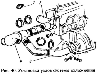
Install the outlet pipe 2 of the cooling jacket with a gasket on the cylinder head and fix it with two nuts. A gasket is installed and the flange of the supply pipe 3 of the coolant pump is attached to the cylinder block. The hoses going to the thermostat are put on the branch pipe and the supply pipe, thermostat 4 is installed and the hoses are fixed with clamps.
Install the housing of auxiliary units with a sealing ring on the cylinder head and fix it with a bolt. When installing the housing, special attention is paid to the position of the sealing ring in the groove, since when the bolt is tightened, the ring may jump out of the groove and bite between the edges of the groove and the surface of the cylinder head. If the o-ring has marks «snacking», then it must be replaced with a new one.
Install the fuel pump with a heat-insulating spacer, with gaskets and a pusher (see sect. «Fuel pump»).
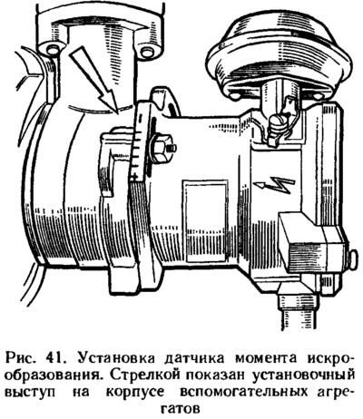
Lubricate with engine oil and put an o-ring on the flange of the spark moment sensor. Attach the sensor to the accessory housing in such a position that the middle mark on the sensor flange is against the mounting lug on the accessory housing (pic. 41). The sensor roller is connected to the camshaft shank in only one position. Therefore, before installation, turn the roller so that the cams of the roller clutch enter the grooves of the camshaft shank.
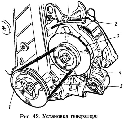
Attach bracket 4 to the cylinder block (pic. 42) with support for the front suspension of the power unit. The tension bar 2 of the generator is fixed with an eye on the cylinder head and the generator 3 is installed by attaching it to the tension bar and to the bracket 4 of the front suspension support of the power unit. Pulley 1 of the generator drive is put on the crankshaft and secured with a bolt and washer. Belt 5 is put on the pulleys of the crankshaft and generator and its tension is adjusted, as indicated in sec. «Engine adjustment».
Put a gasket on the cylinder head studs, install and secure the intake pipe with the bracket for the intermediate carburetor drive lever and the return spring. Install the carburetor with a gasket, fix it with nuts and close it with a technological plug from above. Do not tighten nuts or secure a hot carburetor. Install the throttle actuator linkage by attaching it to the carburetor and to the intermediate lever on the intake pipe.
Put the crankcase exhaust ventilation hose on the nozzles of the cylinder head cover and the rear oil seal holder. Secure the hose with clamps. Install the oil level indicator so that the oil level indicator knob is in a vertical position, otherwise the indicator readings will be distorted.
Install the gasoline supply hose from the fuel pump to the carburetor and secure it with clamps. Install the vacuum regulator hose for the spark torque sensor, as well as the crankcase ventilation hose from the cylinder head to the carburetor.
They put on the outlet pipe of the cylinder head and on the inlet pipe of the coolant pump the hoses leading to the heater and fix them with clamps.
Pour oil into the engine through the neck on the cylinder head cover.
Notes
1. Size D see table. 5. For fitting pistons ∅ 82 mm (engines 11113) similar bushings with diameters increased by 6 mm can be used.