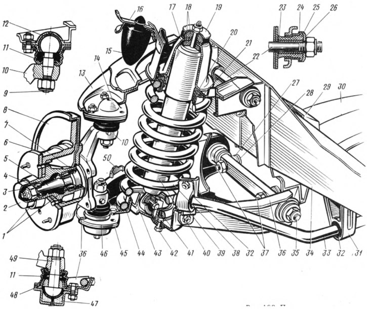
Upper 13 and lower 36 suspension arms are connected to the pivot pin 10 by ball joints. The upper ball joint 14 is attached with three bolts to the upper suspension arm. The bearing 12 is located in the hinge body, the base of which is resin, and the friction surface is Teflon fabric, tightly fitting the spherical surface of the pin 9. The details of the hinge are protected from contamination by a reinforced cover 11. The pin is installed with a conical part in the conical hole of the pivot pin and secured with a self-locking nut. During operation, the hinge parts are not lubricated.
The lower ball joint 45 is connected to the pivot pin and suspension arm in the same way as the upper joint. In the body 46 of the hinge is a pin 49 with a hemispherical head. A ceramic-metal bearing 48 with a hemispherical surface is put on the pin shaft. Insert 47, made of oil-resistant rubber, is inserted with an interference fit into the lower part of the body. A plastic layer is applied to the surface of the insert in contact with the hemisphere of the finger (nylon blend with molybdenum sulfide). There is a hole in the lower part of the hinge body through which the hinge is lubricated. It is closed with a conical stopper.
The upper arm 13 of the suspension is connected by an axle 22 to the front end of the body, and the lower arm 36 is suspended by bolts 37 to the cross member 30 of the suspension by means of an axle 35, which is attached with brackets to the spars. Distance washers 28 and adjusting washers 27 are installed between the axis of the lower rachat and the cross member.
By changing the number of washers 27, the longitudinal angle of inclination of the axis of rotation and the camber angle of the front wheels are adjusted. Both suspension arms are connected to the axles through rubber-metal hinges, which ensure backlash-free connection of these parts. Such a hinge includes a rubber bushing 25, outer 24 and inner 23 metal bushings. A washer 26 is installed between the hinge and the nut.
The spring 38 rests with its upper end through the support cup 21 with a rubber gasket 20 on the front end of the body. The lower end of the spring rests on the support cup 44 of the lower arm. According to the length under a load of 435 kgf, the front suspension springs are sorted into groups A and B. Group A springs are marked with yellow paint, and group B springs are green. The upward movement of the front wheel is limited by the stop of the upper arm 13 against the rubber buffer 15 installed in the bracket 16.
Lateral roll of the body when turning the car is reduced by the anti-roll bar, made in the form of a rod 33 of spring steel. The ends of the rod are attached to the brackets of the lower suspension arms with clips 39 through rubber cushions 32. The rod itself is attached to the side members 34 by two brackets 31, in the holes of which rubber bushings are located. Shock absorbers 40 are attached to the lower suspension arms. The shock absorber rod passes through the hole in the support cup 17 and is fastened with a nut. Rubber cushions 18 are installed between the shock absorber casing and the glass, as well as between the support washer and the glass. The shock absorber is attached to the lower arm by means of a bracket 43 and bolts 41, 42.
The wheel hub 6 is mounted on the trunnion 5 of the steering knuckle on two tapered roller bearings 1, which are pressed by an adjusting nut 3. Between the nut and the outer bearing there is a thrust washer 4 with a mustache included in the groove of the trunnion, due to which it is kept from turning when the nut is tightened. On the inside, a self-clamping gland 7 is installed in the hub nest. From the outside, the hub cavity is closed with a cap 2, which is pressed into the hub. The brake disc 8 and the clamping ring are attached to the hub flange with two guide pins, and the wheel disc is bolted.
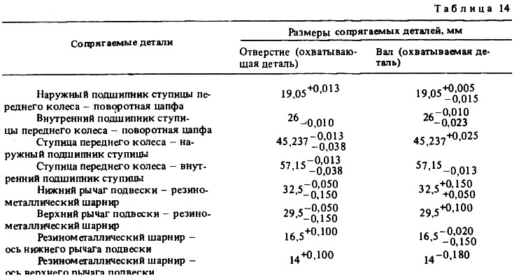
The dimensions of the main mating parts and the limits of permissible wear during operation are given in Table. 14.