
Deformation of the axis of the lower arm is detected by inspection.
The deformation of the front suspension cross member is checked in the following order:
- unscrew the nuts for fastening the axles of the lower levers so that in the resulting gap between the washer 28 (see fig. 100) and the mating surface of the cross member fit the leg of the caliper close to the rod of the front bolt;
- measure the length of the cross member between the planes of installation of the axes of the lower levers (left and right) in the area of the front bolts. The distance must be (611±1) mm. The cross member must be changed if it is deformed so that the wheel alignment angles cannot be adjusted.
The condition of rubber-metal hinges is checked in the following order:
- making sure that there is no deformation of the suspension arms, the axis of the lower arm, hang the front wheels of the car;
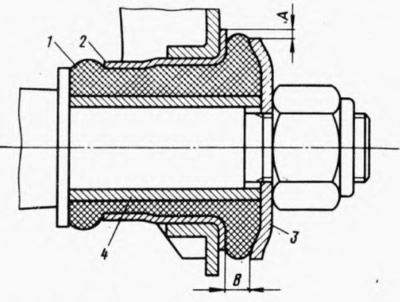
- measure the radial displacement A (pic. 101) outer sleeve 2 relative to the inner sleeve and the distance B between the thrust washer 3 and the outer end of the outer sleeve 2. Rubber-metal hinges are replaced if it is impossible to adjust the camber (when all washers are removed from under the axis of the lower arm), at breaks and unilateral "buckling" rubber 1, with radial displacement A over 2.5 mm and if dimension B does not fit within 3-7.5 mm for the lower arm and 1.5-5 mm for the upper arm. If dimension B is outside the specified limits, check that the rubber-metal joint is pressed into the lever seat correctly.
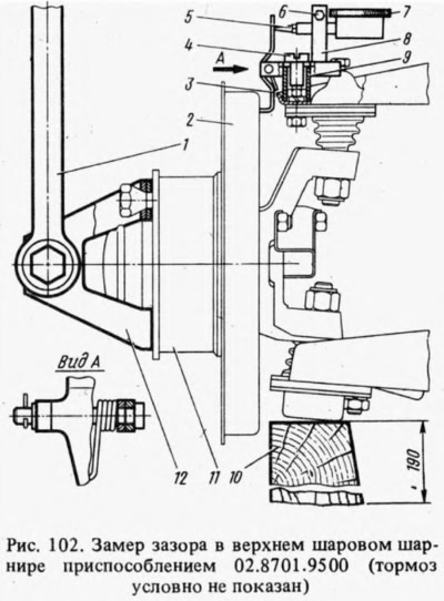
The clearance in the upper ball joints is checked using tool 02.8701.9500. To do this, install the car on a flat horizontal platform with a hard surface, raise the front of the car and remove the wheel. Substitute a wooden block under the lower ball joint 10 (pic. 102) 190 mm high and lower the car onto it. The bushing 9 is installed on the nut of the upper hinge fastening bolt closest to the casing, then the base 8 is put on the bushing and it is slightly fixed with a screw. indicator 7 until it stops its legs 5 into the lever 3 with an interference of 2-3 mm and tighten the bolt 6. Attach the bracket 12 to the hub 11 with two bolts, put the torque wrench 1 on the hex head of the axis of the bracket 12 and turn the key to the car with a torque of 20 kgf·m and from him. Both indicator readings are summed up. The amount should not exceed 0.8 mm.
The condition of the lower ball joints is checked in the following order:
- install the car on a flat horizontal platform with a hard surface and raise the right front of the car, then remove the wheel;
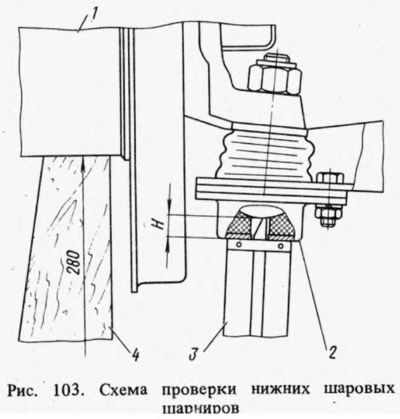
- installed under hub 7 (pic. 103) a wooden block 4 280 mm high and the car is lowered onto it, the lower part of the hinge 2 is cleaned of dust and dirt and the conical plug is unscrewed;
- measure the distance H with a caliper depth gauge 3, as shown in the diagram. If H≥11.3 mm, then the hinge is removed from the car and carefully inspected. There should be no cracks on the hinge body, and dirt in the grease. In the presence of dirt in the lubricant, cracks in the hinge housing, as well as at 11.8 mm, the hinge is replaced.
The condition of the body front elements is checked, as indicated in Sec. 7 "Body".