




Contents: Fuel level indicator ↓ Coolant temperature gauge ↓ Oil pressure gauge ↓ Watch ↓ Tachometer ↓ Speedometer ↓
Open large image in new tab »
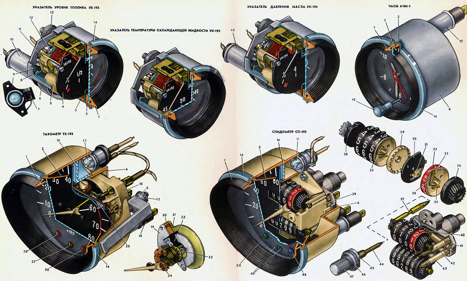
1. Bezel. 2. Glass holder. 3. Light-diffusing bezel. 4. Scale. 5. Bushing. 6. Housing. 7. Instrument protection diode. 8. Instrument mounting bracket. 9. Bridge. 10. Control lamp lamp holder. 11. Frame with coils. 12. Scale illumination lamp lamp holder. 13. Bracket mounting nut. 14. Rim. 15. Arrow setting button. 16. Light filter. 17. Scale illumination lamp. 18. Milliammeter housing. 19. Inner magnetic circuit. 20. Magnet. 21. Outer magnetic circuit. 22. Milliammeter coil. 23. Coil holder. 24. Washer with contact petals. 25. Board with the electronic part of the tachometer. 26. Battery charge indicator light filter. 27. Carburetor choke control indicator light filter. 28. Parking brake indicator light filter and low brake fluid level indicator light. 29. Ring. 30. Peak. 31. Six-tooth gear. 32. Drum. 33. Pawl. 34. Drive disk. 35. Pawl. 36. Pawl spring. 37. Daily counter zero setting shaft. 38. Cam washer. 39. Counter housing. 40. Counter drive shaft. 41. Base. 42. Daily counter drive shaft. 43. Totalizing counter drive shaft. 44. Cable. 45. Bushing. 46. Bushing fastening nut. 47. Daily counter zero setting handle. 48. High beam indicator lamp filter. 49. Direction indicator lamp filter. 50. Exterior lighting indicator lamp filter.
Fuel level indicator
On VAZ-2103 cars, a magnetoelectric fuel level indicator of the UB-193 type is used, which operates together with a BM-150 sensor. It is attached to the instrument panel using a bracket 8 and a nut 13.
The indicator has a stamped steel housing 6, in which a plastic frame 11 with coils and scale 4 is secured with two nuts. A plastic bridge 9 with a lamp holder 10 is riveted to the housing from the rear side. A silicon diode 7 for protecting the vehicle instruments is placed under the bridge, and a socket with an AMN 12-3 fuel reserve control lamp is inserted into the lamp holder 10. A lamp holder for the indicator illumination lamp is also rolled onto the housing from the rear side. A plastic glass holder 2 and a rim 1 are riveted to the housing from the front side with a chrome-plated rim 14.
The device operates in the same way as the coolant temperature indicator UK-191, described on the previous sheet. Depending on the resistance of the sensor, the permanent magnet of the arrow is affected by the total magnetic flux of a certain direction, setting the arrow to a certain position.
Coolant temperature gauge
The device of the UK-193 type is magnetoelectric and has the same design and operating principle as the UB-193 fuel level indicator. It differs in other winding data, as well as the absence of a control lamp and a protection diode. The device operates together with the TM-106 sensor.
Oil pressure gauge
The UK-194 type indicator is magnetoelectric and has the same design as the UB-193 fuel level indicator. It differs in other winding data and the absence of a protection diode. A control lamp for insufficient oil pressure is inserted into lamp holder 9, which is switched on by a sensor of the MM-120 type.
The indicator is used together with the MM3-93A type sensor, which changes the resistance of the electrical circuit depending on the oil pressure in the engine lubrication system.
Watch
The VAZ-2103 uses a clock of the AChZh-1 type with a contactless magnetoelectric balance drive. The clock is installed in the middle part of the instrument panel and is held in place by a plastic ring placed on the clock body and tightly fitting into the opening in the instrument panel.
The watch operates at a supply voltage of 8-16 V and consumes no more than 50 mW of power at a supply voltage of 13 V and a temperature of 20°C. The maximum error in running does not exceed 4 minutes in 96 hours at a supply voltage of 13 V and a temperature of 20 C.
The clock is dustproof. The case is stamped steel. A ground plug is riveted to the case on the back side and a lamp holder 12 is rolled for the clock lighting lamp, which is a miniature lamp of the AMN12-3 type.
Tachometer
On VAZ-210Z cars, an electronic tachometer of the TX-193 type is used. It has a plastic housing 6, to which a plastic glass holder 2 and a rim 1 are attached at the front with a metal chromed edge, and at the back, the housing of the 18 milliammeter is attached with three screws.
The principle of operation of the tachometer is based on measuring the frequency of voltage pulses in the primary circuit of the engine ignition system. As described above (in "Ignition System"), during one revolution of the distributor shaft, the breaker contacts open and close four times. Consequently, during one revolution of the shaft, four current and voltage pulses are created in the primary circuit of the ignition system. The higher the engine crankshaft speed, the higher the pulse frequency.
Voltage pulses are taken from the end of the primary winding of the ignition coil and fed to the input of the current pulse generator, which feeds the milliammeter coil. Depending on the pulse frequency, the average value of the current passing through the milliammeter coil winding changes. The higher the engine crankshaft speed, the higher the pulse frequency, the higher the average value of the current feeding the milliammeter coil winding, and the greater the deviation of the device needle.
The pulse former is a waiting multivibrator on two transistors. The winding of the milliammeter coil is included in the collector circuit of one of the transistors. The multivibrator is mounted on a 25-plate made of foil-clad getinax, attached to the milliammeter case.
Information taken from the website: www.VAZbook.ru
The milliammeter used is of the magnetoelectric type. Its magnetic system consists of a permanent magnet 20, clamped between two magnetic circuits - external 21 and internal 19. The magnet and magnetic circuits are attached to a plastic housing 18. The internal magnetic circuit has a ring part, which is covered by a coil 22, fixed on a holder 23.
The milliammeter axis rotates in two bushings. The front bushing is fixed in the housing 18, and the rear one is attached to the external magnetic circuit 21. The ends of the axis are lubricated during assembly with a special silicone liquid, which has a damping property - it dampens the oscillations of the pointer when the car is moving.
The electric current flowing through the winding of the coil 22 creates a magnetic field around it. As a result of the interaction of the magnetic fields of the coil and the permanent magnet 20, a force acts on the coil that overcomes the resistance of the springs and turns it together with the axis and the pointer at a certain angle. This angle is greater, the greater the magnitude of the current flowing through the winding of the coil.
Speedometer
The VAZ-2103 cars use the SP-193 speedometer. It is installed on the instrument panel and is attached to it with the same brackets and nuts as the TX-193 tachometer.
The speedometer has a pointer speed indicator and two counters: a totalizer and a daily distance traveled counter, the readings of which can be set to zero using handle 47. The mechanisms of the speed indicator and the totalizer are the same as those of the speedometer in the KP-191 instrument cluster of the VAZ-2101 car.
The speedometer housing is plastic. In the upper part there is a compartment covered with a blue diffuser 16. This compartment contains a scale illumination lamp 17. In the lower part of the housing there is a compartment divided by partitions into three sections, in which there are control lamps. The light from the lamps passes through colored plastic light filters 48, 49 and 50, attached with adhesive tape to the scale.
The counters are installed in a plastic housing 39 and are driven by rollers 42 and 43 from roller 40 installed in a metal cast base 41. The device of the total counter is described on the previous sheet. Therefore, only the daily counter is described below.
The daily counter has four drums with numbers. The primary drum 32 is red. It counts hundreds of meters traveled. The other drums count kilometers.
Just as in the summing counter, between the drums of the daily counter there are cheeks 30 with six-toothed gears 31, through which rotation is transmitted from one drum to another. But in the drums of the daily counter the toothed crown is made not in the drums, but on a separate part - crown 29. The crown is connected to the drums through the pawl 35.
Each drum has two pawls: 33 and 35 with a plate spring 36. Pawls 33 enter a special groove made along the axis of the drums. The pawls prevent the drums from turning around the axis in the direction of decreasing the count. Pawls 35 enter the recesses of the toothed rims 29 installed in the drums. Through the pawls, the rim rotates the drum in the direction of increasing the count.
The daily counter operates as follows. The roller 42 rotates the drive disk 34, which rotates the drum 32 via the pawl 35. During one full revolution, the drum 32, with two teeth on its other side, rotates the six-tooth gear 31 by 120°, and that, via the crown 29, rotates the next drum by 1/10 of a revolution.
When resetting the daily counter readings, the shaft 37 rotates the drum axis via the gears in the direction of increasing the count. The pawls 33 enter the groove of the axis and all the drums rotate together with it until the cam washer 38 is fixed by a flat spring. This spring is installed in the housing 39 and fixes the washer in such a position when all the drums show zero in the scale window.
Roller 37 is driven into rotation via cable 44 from handle 47, which is attached to the instrument panel using bushing 45 and nut 46. To set the counter readings to zero, handle 47 must be rotated counterclockwise. To avoid damaging the counter, this should be done on a stationary vehicle.