
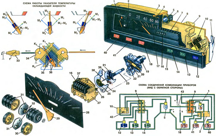
1. Control lamp. 2. Fuel gauge. 3. Body. 4. Frame. 5. Instrument lighting lamp. 6. Lamp holder. 7. Protective glass. 8. PCB. 9. Block of plugs. 10. Coolant temperature gauge. 11. Instrument cluster holder. 12. Control lamp high beam headlights. 13. Control lamp for outdoor lighting. 14. A control lamp of indexes of turn. 15. Welt. 16. Distance meter. 17. Speedometer. 18. Battery charge control lamp. 19. Foundation. 20. Primary roller drive counter. 21. Permanent magnet. 22. Thermal compensator. 23. Drive roller. 24. Screen. 25. Return spring. 26. Secondary counter drive roller. 27. Counter case. 28. Speedometer scale. 29. Speedometer needle. 30. Drum. 31. Cheeks. 32. Six-toothed wheel (tribka). 33. Coolant temperature indicator sensor. 34. The frame of the coils of the coolant temperature gauge. 35. Permanent magnet. 36. Magnet balancers and arrows. 37. Spring fastening counter. 38. The axis of the arrow of the speedometer. 39. Cartridge. 40. Parking brake warning lamp (flashing light) and brake fluid level (constant light). 41. Oil pressure warning lamp. 42. Device protection diode. 43. Contact jumper.
a, b, c - plugs on the printed circuit board
Automotive instrumentation is somewhat different in design from stationary instruments used in laboratory practice. This is because, at low manufacturing cost, they must operate reliably under harsh operating conditions. For example, they must withstand vibration and shaking, operate with significant temperature fluctuations, be insensitive to changes in the supply voltage within 11... 15 V, etc. parameters. Therefore, the arrows of the instruments are wide and straight, and there are usually no small divisions on the scales and there are often color zones of dangerous modes
Instrument cluster
On cars «Oka» all control devices are united in one common node - a combination of devices of the KP-191A2 type. It is similar in design to the instrument clusters KP-191 and KP-191A, which were used on cars «Zhiguli» VAZ-2101, VAZ-2102, VAZ-21011, VAZ-21013, and can be installed on these vehicles.
The main difference between the instrument cluster KP-191A2 and KP-191 and KP-191A is the way the indicator lamp 18 of the battery charge is turned on. One of the lamp leads is connected to the plug «4» V «orange» block 9. The second conclusion on cars «Oka» should connect with «+» power source, and «Zhiguli» - with mass. Therefore, in order for the KP-192A2 instrument cluster to be installed on «Oka» and on «Zhiguli», three plugs are riveted to the printed circuit board 8 - a, b, c, connected by a contact jumper 43. When installing the instrument cluster on «Oku» plug 6 (lamp output 18) must be connected by a jumper to the plug in («+» power supply), and on cars «Zhiguli» - with plug a (i.e. with mass).
The instrument cluster contains the mechanisms of three devices: fuel level indicator 2, speedometer 17 and coolant temperature indicator 10. In addition, it contains seven control lamps, one of which (1 - fuel reserve) installed in the fuel gauge.
Four control lamps 1, 18, 40 and 41 have a red light filter. They warn the driver about the inadmissibility of movement or the need to take some action: for example, fill the fuel tank if lamp 1 is on, or troubleshoot the generator system if lamp 18 is on. Three lamps - 12, 13 and 14 are informational and are equipped with green or blue filter. They signal the driver to turn on any lights, such as direction indicators (lamp 14) or high beam headlights (lamp 12). The instrument cluster is installed in the instrument panel socket and is fixed with two spring holders 11. To remove it (e.g. to replace pilot lamps), it is necessary to bend these holders under the instrument panel to the instrument cluster housing.
The instrument cluster has a rectangular plastic housing 3 with compartments that house the instrument mechanisms and control lamps. Outside, the case is closed with a plastic frame 4 with a protective glass 7 and multi-colored light filters of control lamps. The outer side of the frame is painted black. The frame is attached to the body with a chrome-plated metal welt 15.
Electrical connections between devices, control lamps and output plugs are made by printed wiring on board 8 of foil-coated getinaks. This greatly simplifies the manufacture of the instrument cluster. The printed circuit board is varnished and attached to the outside of the back of the case. Together with the printed circuit board, plastic blocks of 9 plugs are attached to the case, and the plugs themselves are connected to the printed circuit board using rivets. The printed circuit board also serves to mount control lamps and instrument lighting lamps. Pilot lamps of the AMN12-3 type are inserted into plastic cartridges 6, and those into the holes of the printed circuit board.
Between conductors «+» and «weight» supply voltage, a diode 42 of type D-226B or a similar diode manufactured by VNR is installed. Through it, the reverse current pulses that occur in the electrical system are closed to ground. This prevents demagnetization of the permanent magnets of the fuel level and coolant temperature gauges.
The speedometer type SP-191 A, installed in the instrument cluster, has two functional units with a common drive. The first converts the speed of rotation of the drive hall into the deflection of the needle (this is the speedometer). The second node 16 converts the rotation of the roller into an indication of the vehicle's mileage on the counting drums. This is a counting node (also called an odometer). The speedometer units are driven by a flexible shaft from the speedometer drive (see ch. 19), mounted on the clutch housing.
The speedometer is attached to the instrument cluster housing with two screws, one of which is sealed. The speedometer scale has white divisions from zero to 160 km / h every 10 km / h, as well as three red marks corresponding to speeds of 38, 62 and 98 km / h. These risks indicate the limit speeds in first, second and third gears, exceeding which can lead to engine failure
The speed indicator mechanism consists of a permanent magnet 21 mounted on a drive roller 23, and an aluminum card 39 fixed together with an arrow on an axle 38. The roller rotates in a cast metal base 19, to which a steel screen 24 and a plastic case 27 of the counter are attached with two screws. The screen closes the card and is designed to increase the magnetic flux passing through it, which increases the sensitivity of the speed indicator. One end of the axis rotates in the hole of the screen, and the other in the hole of the body 27. The ends of the axis are lubricated with a special silicone fluid to dampen the arrow - to reduce its vibrations when the car is moving. In the middle part of the axle there is a bushing with the end of the spiral return spring 25 fixed in it.
When the magnet rotates, the magnetic force lines penetrate the card and induce an EMF in it, under the action of which eddy currents arise in the card. These currents create their own magnetic field of the card. As a result of the interaction of the rotating magnetic field of the permanent magnet and the magnetic field of the card, a torque acts on it, which turns the card, and with it the arrow, in the direction of rotation of the magnet. The torque acting on the card is balanced by the counteracting moment of the helical spring 25. The higher the frequency of rotation of the magnet, the greater the torque, the greater the deflection of the arrow.
As the temperature rises, the electrical resistance of the card to eddy currents increases. At the same time, its magnetic field decreases and, if appropriate measures are not taken, the card with an arrow will rotate at a smaller angle. The speed indicator reading will be incorrect. To reduce the effect of temperature on the deflection of the arrow, a temperature compensator 22, or, as it is also called, a magnetic shunt, is fixed next to the magnet on the drive roller. It is a thin steel plate. The magnetic flux of a permanent magnet is divided into two parts. One part of it closes through the card, and the other through the temperature compensator. As the temperature rises, the magnetic resistance of the temperature compensator increases, the magnetic flux through it decreases, and through the card increases. The EMF induced in the card increases and compensates for the increase in its resistance. Therefore, the eddy currents of the card with increasing temperature change slightly and the speedometer needle deviates almost by the same value.
The odometer mechanism consists of six plastic drums 30 mounted on a common axis. Five of them are marked with numbers from zero to nine, indicating kilometers, and there are no numbers on the primary drum. Fixed cheeks 31 with plastic six-tooth wheels are installed between the drums (tribes) 32. Drums with numbers on one side have a full gear rim of internal gearing, and on the other side - only two teeth. The primary drum also has only two teeth. When turning one of the drums a full turn, two of its teeth on the left side turn the gear wheel 32 by 120°, and the adjacent left drum is rotated by this gear wheel by 1/10 of a turn. The next number appears in the scale window. The maximum value of the meter reading is 99999 km, after which it starts counting again from zero. The axis of the drums is fixed in the housing 27 using the spring 37.
The rotation from the roller 23 is transmitted to the primary drum through the rollers 20 and 26 with three worm gears having a gear ratio of 1:10. Thus the total gear ratio is 1:1000. One revolution of the drive roller 23 corresponds to 1 m of the distance covered.
Coolant temperature gauge. A magnetoelectric coolant temperature indicator of the UK-191 B type is installed in the instrument cluster. It works in tandem with the TM-106 sensor and is attached to the printed circuit board 8 with three pins, which at the same time are the contact leads of the coils. There are two risks and a red zone on the pointer scale. The first risk corresponds to 30°C, the second to 60°C, and the beginning of the red (dangerous) zones - 108°С.
The pointer consists of a plastic frame 34, on which coils are wound, and an axis with an arrow, a permanent magnet 35 and balancers 36, which make up the movable system of the pointer. The center of gravity of the moving system is located in such a way that when the device is turned off, the arrow deviates to the left edge of the scale. The axis of the arrow rotates in two bearings, one of which is made in the form of a screw, and with its help during assembly, the free play of the axis is adjusted. In the socket of this screw there is a special damping silicone fluid that does not allow the needle to vibrate when the car is moving.
Coils have three windings: K1, TO2 and K3. Winding K3 wound perpendicular to the windings K1 and K2, and the windings K1 and K2 - towards each other. Thus, three magnetic fluxes M1, M2 them3, created by three windings. Their direction is determined by the gimlet rule. Instruments with this principle of operation are also called ratiometric.
The current from the power source passes first through the winding K1, and then branches into two chains. One of them closes to ground through series-connected coils K2 and K3, and the other through the sensor 33. whose resistance varies depending on the temperature of the coolant. In connection with a change in the resistance of the sensor, the strength of the currents in the windings and the magnetic fluxes they create change. Total magnetic flux MS, acting on a permanent magnet, is determined by the parallelogram rule.
If the engine is cold, then the resistance of the sensor is significant. the current strength in the sensor circuit is small and the magnetic flux M1 less than M2. In this case, the total magnetic flux M1 keeps the pointer at the beginning of the scale. With an increase in the temperature of the coolant after starting the engine, the resistance of the sensor decreases and, consequently, the strength of the current passing through it and the winding K increases1, and the current through the windings K2 and K3 decreases. As a result, the magnetic flux M1 increases, flows M2 them3 decrease, and the total magnetic flux MS changes direction and turns the pointer towards the middle of the scale. When the coolant is overheated, the resistance of the sensor decreases significantly, the current strength through the winding K1 and magnetic flux M1 increase even more with a decrease in magnetic fluxes M2 them3, total magnetic flux MS changes direction even more and deflects the needle into the red zone of the scale.
If the sensor resistance is 1000... 5000 Ohm, the pointer should be at the beginning of the scale, and if the resistance is 98... 110 Ohm - at the beginning of the red zone (at pointer temperature 20°С).
Fuel gauge. In the instrument cluster, a fuel level indicator of the UB-191B type is installed. Just like the coolant temperature gauge, it is magnetoelectric and has the same design and principle of operation. It differs in winding data, attachment points to the printed circuit board and the relative position of the permanent magnet, pointer and balancers.
The pointer is used in tandem with the sensor type 34.3827. This sensor also turns on the control lamp 1 of the fuel reserve, if less than 4... 6 liters of gasoline remain in the tank. With a sensor resistance of 285... 335 Ohm, the arrow should be at the beginning of the scale, with a resistance of 100... 135 Ohm - in the middle of the scale, and with a sensor resistance of 0... 25 Ohm - it should deviate to the end of the scale.
Relay-interrupter of a control lamp of a parking brake
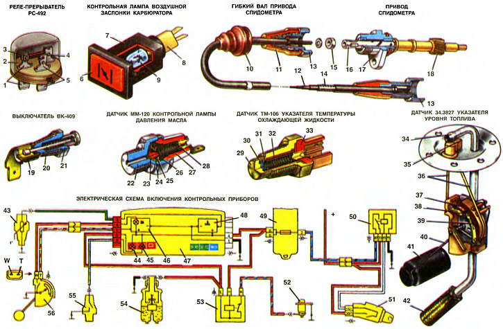
1. Stand-plug «+». 2. Foundation. 3. Bimetallic plate. 4. Stand-plug «L». 5. Stand-plug «—». 6. Light filter. 7. Body. 8. Lamp holder. 9. Lamp A12-1.2. 10. Cover. 11. Protective sleeve. 12. Flexible shaft. 13. Nut. 14. Flexible shaft armor. 15. Sealing gasket. 16. Roller driven gear. 17. Speedometer drive housing. 18. Driven gear. 19, 26. Moving contact. 20. Stock. 21. Switch housing. 22, 29. Sensor housing. 23. Diaphragm. 24. Pusher. 25. Fixed contact. 27. Insulating cap. 28. Filter plug. 30. Thermistor. 31. Spring cup. 32. Insulating cartridge. 33. Plug holder. 34. Receiving tube. 35. Plug connector. 36. Connecting wires. 37. Resistor. 38. Fixed contact to turn on the fuel reserve warning lamp. 39. Resistor slider. 40. Lever. 41. Float. 42. Filter. 43. Coolant temperature indicator sensor. 44. Warning lamp parking brake and brake fluid level. 45. Oil pressure warning lamp. 46. Fuel level indicator with a reserve control lamp. 47. Instrument cluster. 48. Coolant temperature gauge. 49. Fuse box. 50. Ignition relay. 51. Ignition switch. 52. The switch of a control lamp of a parking brake. 53. Relay-breaker of the parking brake warning lamp. 54. Brake fluid level sensor. 55. Sensor control lamp oil pressure. 56. Fuel gauge sensor.
a - a distinctive belt
Relay-breaker type RS-492, suspended on wires behind the instrument cluster, is designed to produce intermittent burning of the parking brake warning lamp. The relay-breaker has a plastic base, in which three rack-plugs 1, 4 and 5 are fixed, having the designation, respectively «+» «L» and «—». To stand-plug «L» a bimetallic plate 3 is welded with a winding of nichrome wire, insulated from the plate with asbestos paper. Winding resistance 26 Ohm at 20°C. One of its ends is welded to the stand-plug «—», and the other to the contact riveted to the end of the bimetallic plate. From above, the relay-breaker is closed with an aluminum stamped casing.
When the bimetal strip is cold, it is pressed against the plug «+» and the contact of the plate is closed with the contact of this plug. When closing the contacts of the switch 52 (parking brake lever up) current flows along the path: power supplies - contacts «30» and «87» ignition relay 50 - plugs «2» and «B» fuse box 49, and then divided into two circuits. One closes to ground along the way: instrument cluster 47 - parking brake warning lamp 44 - plug «L», bimetallic strip 3 and through the closed contacts of the relay-breaker 53 to the plug «+» then switch 52 - ground. In this case, the lamp 44 is lit. Another circuit shorts to ground along the way: plug «B» fuse box - plug «—», the winding of the relay-breaker and through its closed contacts to the plug «+» - switch 52 - ground.
The current flowing through the winding of the breaker relay heats it up. The bimetallic plate 3 bends from heating, and the contacts of the relay-breaker open. The current in both circuits stops and the lamp goes out. The bimetallic plate cools down and takes its former shape. The contacts of the relay-breaker close again, including the control lamp, and the described cycle is repeated at a frequency of 60... 120 times per minute, creating a flashing of the control lamp 44 of the parking brake.
The control lamp 44 also performs a second function. It signals a low fluid level in the hydraulic brake fluid reservoir. When closing the contacts of the sensor 54, located in the tank (see ch. 28), current from plug «B» the fuse box goes through lamp 44 and closes to ground through sensor 54. Lamp 44 is lit without blinking, signaling the need to fill the tank with liquid.
The VK-407 switch is used as switch 52 of the parking brake indicator lamp (see ch. 35), but with plug rotated 90°. It is mounted on a special bracket under the parking brake lever.
Carburetor choke warning light switch
Switch type - VK-409. It is mounted on the steering bracket above the choke control knob. In the body 21 of the switch, the rod 20 moves, at the end of which a movable contact 19 is fixed on a plastic insulating sleeve. When the air damper control handle is pulled out, the movable contact 19 is pressed against the switch body by a spring and the control lamp power circuit is closed.
Carburetor choke control lamp
The control lamp type 2202.3803-33 is installed on the instrument panel to the left of the steering column and is held in the instrument panel socket with the help of spring protrusions of the housing. The lamp has a plastic housing 7 with an orange light filter. A cartridge 8 with a miniature lamp of the A12-1.2 type is inserted into the body.
Speedometer drive
The speedometer drive is installed in the lower part of the clutch housing and is attached to it with a stud and nut. It is a steel roller 16 with a plastic driven gear 18 molded on it (day off) the end of the roller rotates in a ceramic-metal sleeve. pressed into an aluminum housing 17. At this end of the roller there is a socket for the tip of the flexible shaft of the speedometer drive. The other end of the roller enters a sleeve pressed into the clutch housing. The driven gear 18 is engaged with the drive gear mounted on the differential box. The gear ratio of these gears is 1.65:1.
The speedometer drive on VAZ-1111 cars is the same. as on VAZ-2108 cars, but differs in the number of teeth of the driven gear (14 instead of 16 teeth for the VAZ-2108). Therefore, to eliminate errors, the drive of the speedometer of VAZ-1111 cars has a distinctive belt a near the driven gear.
Flexible speedometer drive shaft
The flexible shaft is used to transmit rotation from the speedometer drive. located in the engine compartment, to the speedometer mechanism in the instrument cluster installed in the passenger compartment. The flexible shaft is the same as on VAZ-2108 cars. To distinguish it from the flexible shafts of other vehicles, it has a white plastic band on its shell.
The flexible shaft consists of armor 14, twisted from a steel tape, and the flexible shaft 12 itself, rotating in the armor. For normal operation of the flexible shaft, it is necessary that it does not have bends with a radius of less than 100 mm. Nipples with nuts 13 are fixed at the ends of the armor for connection to the speedometer drive and instrument cluster. Outside, a plastic shell is put on the armor. The armor serves to protect the flexible shaft from damage and at the same time acts as a flexible shaft bearing, for which it is lubricated inside with oil.
The flexible shaft 12 is wound from three layers of steel wire, with adjacent layers wound in opposite directions. The core of the shaft is made of five steel wires. The ends of the flexible shaft are pressed to give them a square cross section. With these ends, the shaft enters the corresponding sockets of the speedometer drive rollers and instrument cluster. The rubber cover 10 prevents the penetration of dust and moisture into the passenger compartment through the hole in the front panel of the car, through which the flexible shaft passes.
Oil pressure warning light sensor
The MM-120 type sensor is used in the alarm circuit for emergency low oil pressure in the engine lubrication system. It turns on the control lamp 45 with a red light filter in the instrument cluster. The sensor is wrapped in the oil filter mounting flange.
A thin polyester diaphragm 23 is clamped in the steel case 22 of the sensor, dividing the sensor into two cavities. Oil from the engine lubrication system enters the high-pressure cavity and presses on the diaphragm. Fixed 25 and 26 movable contacts are installed in the low pressure cavity, as well as a spring that counteracts the deflection of the diaphragm and presses the movable contact to the fixed one. The diaphragm, together with the fixed contact and the insulating cap 27, is rolled up in the housing. The fixed contact is connected to ground through the housing, and the movable contact is connected to the output plug through a spring and a contact sleeve. The contact sleeve has a hole closed by a plug-filter 28 through which the supra-diaphragmatic cavity of the sensor communicates with the atmosphere.
If the pressure in the engine lubrication system is below 20...60 kPa (0.2...0.6 kgf/cm2), then the movable contact is pressed against the fixed contact by a spring, the power supply circuit of the control lamp 45 is closed and the lamp is on. As soon as the oil pressure exceeds 20...60 kPa (0.2...0.6 kgf/cm2), it bends the diaphragm and, overcoming the resistance of the spring, pushes the movable contact from the fixed contact with the pusher. The control lamp power supply circuit opens and the lamp goes out.
Temperature gauge sensor
As a sensor for the temperature indicator, a TM-106 type sensor is used. It wraps into the cylinder head at the rear of the engine. The TM-106 sensor is of the thermistor type. The sensing element in it is the thermistor 30. It is a non-wire semiconductor resistor that sharply changes its resistance when the temperature changes. For example, at a temperature of 30°C, the resistance of the thermistor is about 1500 ohms, and when the temperature rises to 110°C, it decreases to 100 ohms.
The body 29 of the sensor is brass. It has a conical thread and a hexagonal turnkey head. The thermistor 30 is pressed by a spring to the bottom of the case, i.e., one side of it is connected to ground through the case. The other side of the thermistor is connected through a spring to an output plug fixed in a plastic holder 33. The spring, the cup 31 of the spring and the side surface of the thermistor are isolated from the walls of the housing with a paper cartridge 32. The holder 33 of the plug is rolled into the housing. A rubber seal is installed between the body and the holder for tightness.
Fuel gauge sensor
To control the level of fuel in the tank, on cars «Oka» sensor type 34.3827 is used. It is used in conjunction with the UB-191B fuel gauge installed in the instrument cluster.
The sensor flange is attached to the fuel tank with six screws. A receiving tube 34 with a mesh filter 42 is welded to the sensor flange, through which fuel is sucked from the tank. A plastic case of a variable resistor is fixed on the base plate welded to the receiving tube. Resistor 37 is wound on a flexible plastic plate with nichrome wire and inserted into the case. The lower end of the resistor through the connecting wire is brought up to the plastic block, and the upper end is not connected to anything. In the case, an axis with a float lever and a slider 39 of the resistor rotates. The slider is electrically connected to the flange through the axle, the base plate and the receiving tube, and the flange, in turn, is connected to the ground with a separate wire, the tip of which is attached under one of the flange fastening screws.
When the fuel level changes, the lever with the float rotates, the slider 39 moves and includes a certain section of the resistor in the electrical circuit. The dependence of the sensor resistance on the fuel level is inverse: the higher the fuel level in the tank, the smaller the resistor section is included in the electrical circuit and, therefore, the lower the sensor resistance. When the tank is empty, the resistance of the sensor is 315...345 Ohm, and when the tank is full, it is less than 7 Ohm.
A fixed contact 38 is also attached to the sensor housing to turn on the fuel reserve warning lamp. This contact is also connected to a corresponding plug in a plastic socket mounted on the flange. The slider 39 has a separate petal, which is closed with a fixed contact 38, if the float is in the lower position. At the same time, the control lamp in the fuel gauge turns on, signaling that less than 4... 6 liters of gasoline remain in the tank.