




Scheme of taking measurements to determine the thickness of the drive gear adjusting ring
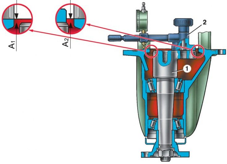
1 – mandrel A.70184; 2 – device A.95690 with indicator; a1 and a2 – distance from the end of the mandrel to the journals of the differential bearings
Main gears
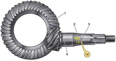
1 – driven gear; 2 – serial number; 3 – correction in hundredths of a millimeter to the nominal position; 4 – leading gear
Installing the inner ring of the rear bearing on the drive gear
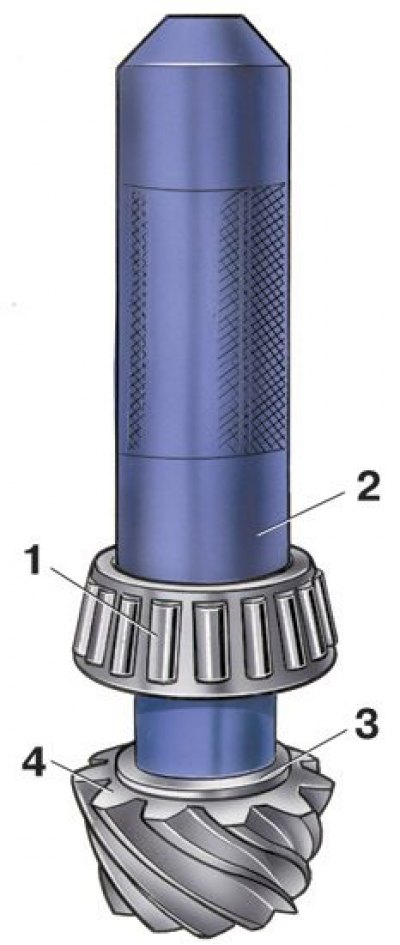
1 – inner ring of the rear roller bearing; 2 – mandrel A.70152; 3 – adjusting ring; 4 – leading gear
1. The correct position of the drive gear relative to the driven gear is ensured by selecting the thickness of the adjusting ring installed between the thrust end of the drive gear and the inner ring of the rear bearing.
2. Select the adjusting ring using the A.70184 mandrel and the A.95690 device with an indicator. Perform the operations in the following order.
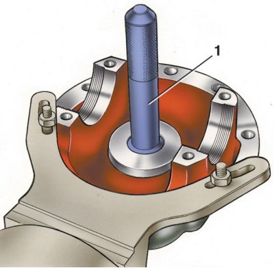
3. Having secured the gearbox housing on the stand, press the outer rings of the front and rear bearings of the drive gear into the housing sockets, using mandrels for this: for the front bearing - A.70185, and for the rear - A.70171 (1 - mandrel A.70171).
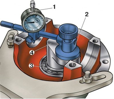
4. On the A.70184 mandrel, simulating the drive gear, install the inner ring of the rear bearing using the A.70152 mandrel and insert the mandrel into the neck of the gearbox housing (1 - indicator; 2 – device A.95690; 3 – rear bearing of the drive gear; 4 – mandrel A.70184).
5. Install the front bearing inner race, pinion flange and, while rotating the drift to correctly install the bearing rollers, tighten the nut to a torque of 7.84–9.8 N·m (0.8–1 kgf·m).
6. Fix the device A.95690 to the end of the mandrel 4 and set the indicator, which has divisions of 0.01 mm, to the zero position by installing its leg on the same end of the mandrel A.70184. Then move the indicator 1 so that its leg stands on the seating surface of the differential box bearing.
7. By turning the mandrel 4 with the indicator to the left and to the right, set it to a position in which the indicator arrow marks the minimum value "a1" (see fig. Measurement diagram for determining the thickness of the drive gear adjusting ring) and write it down.
8. Repeat this operation on the seating surface of the second bearing and determine the value "a2".
9. Determine the thickness "S" of the drive gear adjusting ring, which is the algebraic difference between the values "a" and "b": S = a - b, where a is the arithmetic mean distance from the end face of the mandrel 1 (see fig. Measurement diagram for determining the thickness of the drive gear adjusting ring) to the differential bearing journals a = (a1 + a2)/2, b is the deviation of the drive gear from the nominal position, translated into mm. The deviation value is marked on the drive gear (see fig. Main transmission gears) in hundredths of a millimeter with a plus or minus sign.
10. When determining the thickness of the adjustment ring, take into account the sign of the quantity "b" and its unit of measurement.
Example:
Let's assume that the value "a" set with the indicator is 2.91 mm (the value "a" is always positive), and the deviation "-14" is set after the serial number on the drive gear. To get the value "b" in millimeters, you need to multiply the specified value by 0.01 mm:
b = -14 x 0.01 mm = - 0.14 mm.
Determine the thickness of the adjusting ring for the drive gear in millimeters:
S = a - b = 2.91 mm - (- 0.14 mm) = 2.91 mm + 0.14 mm = 3.05 mm.
In this case, install an adjustment ring with a thickness of 3.05 mm.
11. Place an adjusting ring of the required thickness on the drive gear and press it on using the A.70152 mandrel (see Fig. Installing the inner ring of the rear bearing on the drive gear) inner ring of the rear bearing, removed from the mandrel A.70184. Put on the spacer sleeve.
Attention! When repairing the rear axle gearbox, it is necessary to install a new spacer sleeve if the gearbox housing, main gear pinions or pinion bearings have been replaced. If the specified parts remain the same, the spacer sleeve can still be used.
12. Insert the pinion gear into the gearbox housing and install the front bearing inner race, oil deflector, oil seal, pinion gear flange and washer onto it.
Attention! In order not to damage the seal when pressing it in, it is necessary to press it in not to the stop, but to a depth of 2 mm (permissible deviation "-0.3") between the end of the gearbox housing and the outer surface of the seal.
13. Screw a nut onto the end of the drive gear and, having locked the flange of the drive gear, tighten it (for tightening torque, see. below)