




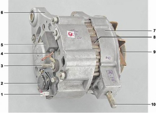
Generator 372.3701: 1 - terminal "B" of the voltage regulator; 2 - voltage regulator; 3 - terminal "30" of the generator; 4 - output "61" (common terminal of additional diodes); 5 - capacitor; 6 - generator rear cover; 7 - Generator front cover; 8 - stator; 9 - pulley; 10 - generator mounting stud to tension bar
The car is equipped with an alternating current generator type 372.3701. It is a three-phase synchronous electric machine with electromagnetic excitation. The generator is mounted on the engine on the right side and is driven by a V-belt from the crankshaft pulley. Through the holes in the covers' lugs, the generator is fastened with a bolt to the engine bracket and with a stud to the tension bar.
Technical characteristics of the generator 372.3701:
| Nominal voltage, V | 14 |
| Maximum output current at 13 V and rotor speed of 5000 rpm, A | 55 |
| Power, W | 770 |
| Weight, kg | 4,4 |
The main parts of the generator are the rotor, stator and covers, cast from aluminum alloy.
Rotor consists of a shaft, on the ribbed surface of which a steel sleeve and steel beak-shaped poles are pressed, which together with the shaft and the rotor sleeve form the core of the electromagnet. The rotor winding is placed on the sleeve between the poles in a plastic frame (excitation winding). The winding terminals are soldered to contact rings mounted on a plastic bushing located on the shaft. The pulley and impeller of the cooling fan are secured to the front end of the rotor shaft using a segment key and a nut. The rotor shaft rotates in two ball bearings mounted in the generator covers. The rear bearing is pressed onto the rotor shaft, and the front bearing is held in the cover by special washers secured with four bolts and nuts.
Stator is assembled from 1 mm thick electrical steel plates. A three-phase winding is placed in the slots on the inner surface of the stator. Each winding consists of six series-connected coils. Some terminals of the phase windings are connected in a star, while others are connected to pairs of diodes of the rectifier unit.
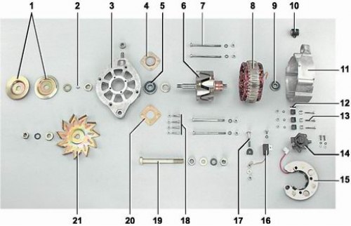
Generator details 372.3701: 1 - pulley; 2 - segment key; 3 - Generator front cover; 4 - outer bearing mounting washer; 5 - Front rotor bearing; 6 - rotor; 7 - tie bolt; 8 - stator; 9 - rear rotor bearing; 10 - buffer bushing; 11 - back cover; 12 - insulating bushings; 13 - bolt; 14 - voltage regulator; 15 - rectifier block; 16 - capacitor; 17 - contact bolt; 18 - bolt; 19 - bolt; 20 - inner bearing mounting washer; 21 - fan impeller
To convert alternating current to direct current, the generator has a built-in rectifier block on six silicon diodes, installed in the rear cover of the generator and secured to it with three bolts. The diode housings are pressed into two aluminum holders for positive and negative diodes, isolated from each other, assembled into a single block. Three diodes have a plus on the housing ("positive diodes"), the other three - a minus ("negative diodes"). A contact bolt of the "30" terminal of the generator is installed on the holder of the positive diodes; the holder is also connected by a wire to the "B" terminal of the voltage regulator. The holder of the negative diodes is connected to the rear cover of the generator - "ground".
Voltage regulator with a brush holder is made as a non-separable unit and is attached with two screws to the rear cover of the generator. It is designed to maintain the nominal voltage in the vehicle's electrical network regardless of the shaft rotation speed.
When the ignition is turned on, the voltage to the excitation winding is supplied to the terminal "B" of the regulator through the battery charge lamp. After the engine is started, the excitation winding is powered by three additional diodes located on the rectifier unit. In this case, the current does not pass through the charge lamp and it does not light. A burning lamp signals a malfunction of the generator circuit. The terminals of the additional diodes are connected to terminal "61" of the generator.
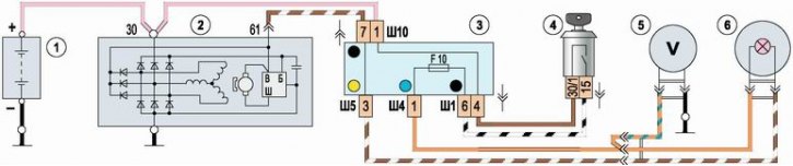
Electrical connection diagram of generator 372.3701: 1 - battery; 2 - generator; 3 - mounting block; 4 - ignition switch; 5 - voltmeter; 6 - battery charge lamp
A capacitor, secured with a screw on the back cover, is connected to the generator's electrical circuit to suppress radio interference.
Some cars are equipped with a 9412.3701 generator, which has a number of design differences: the rear cover is made of plastic, the fan impeller is located inside the generator. To reduce brush wear, the contact rings are made of a smaller diameter. The maximum output current of the generator is 80 A. The "B+" terminal of the generator is connected to the positive terminal of the battery.
Warning! Do not operate the generator with the battery disconnected. This will cause short-term voltages to appear at the "30" terminal of the generator, which may damage the generator voltage regulator and electronic devices in the vehicle's on-board network.