
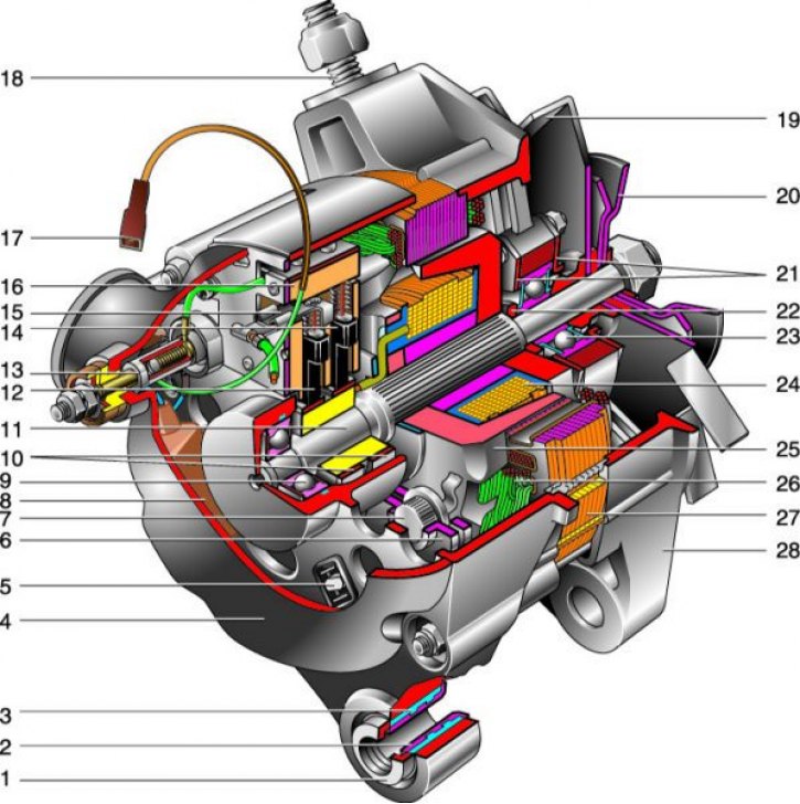
Generator 371.3701: 1 - clamping sleeve; 2 - bushing; 3 - buffer sleeve; 4 - protective cover; 5 - screw fastening the rectifier unit; 6 - rectifier block; 7 - rectifier block valve; 8 - capacitor; 9 - rear bearing of the rotor shaft; 10 - contact rings; 11 – rotor shaft; 12 - brush connected to the output «IN» voltage regulator; 13 - conclusion «30» to connect consumers; 14 - brush connected to the output «W» voltage regulator; 15 - output «IN» voltage regulator; 16 - voltage regulator; 17 - output «61» generator; 18 – a hairpin of fastening of the generator to a tension level; 19 - impeller; 20 - pulley; 21 - bearing mounting plates; 22 - thrust ring; 23 - front bearing of the rotor shaft; 24 - rotor winding; 25 - pole tip of the rotor; 26 - stator winding; 27 - stator; 28 - front cover (drive side).
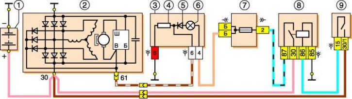
Generator connection diagram 371.3701: 1 - rechargeable battery; 2 - generator; 3 – a combination of devices; 4 - resistor 51 Ohm, 5 W; 5 - diode; 6 – a control lamp of a charge of the accumulator battery; 7 - fuse box; 8 - ignition relay; 9 - ignition switch.
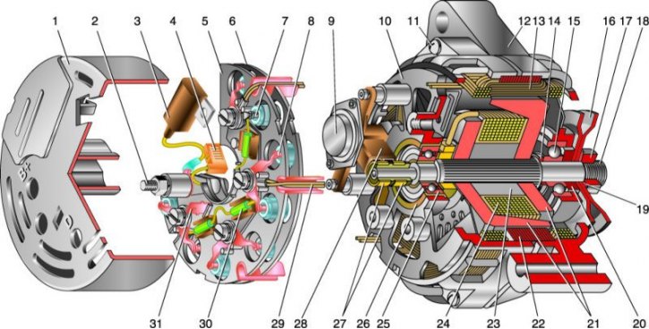
Generator 9412.3701: 1 - casing; 2 - output «IN» to connect consumers; 3 - capacitor; 4 - common output of additional diodes (joins the conclusion «D» voltage regulator); 5 - holder of positive diodes of the rectifier unit; 6 - holder of negative diodes of the rectifier unit; 7 - positive diode; 8 - negative diode; 9 - voltage regulator; 10 - back cover; 11 - coupling screw; 12 - front cover; 13 - stator winding; 14 - thrust ring; 15 - front bearing of the rotor shaft; 16 - pulley; 17 - nut; 18 - rotor shaft; 19 - conical washer; 20 - washer; 21 - pole pieces of the rotor; 22 - stator core; 23 - bushing; 24 - rotor winding; 25 - rear bearing of the rotor shaft; 26 - bearing sleeve; 27 - contact rings; 28 - brush holder; 29 - stator winding leads; 30 - additional diode; 31 - output «D» (common output of additional diodes).
On the VAZ-21213 engine, a generator of type 371.3701 is installed, on the VAZ-21214 engine - of type 9412.3701. These generators are structurally similar and are synchronous AC machines with electromagnetic excitation, with built-in silicon diode rectifier and electronic voltage regulator. The generator rotor is driven from the engine crankshaft pulley by a V-belt.
Technical characteristics of the generator 371.3701
|
Maximum output current (at 13 V and 6000 min -1), A |
80 |
| Voltage, V | 13,2–14,7
|
| Direction of rotation (drive side) | right
|
The stator and generator covers are tightened with four bolts. The rotor shaft rotates in bearings installed in the covers. The bearings are greased at the factory to last the lifetime of the generator. The rear bearing of the generator 9412.3701 is pressed onto the rotor shaft and is pressed by the rear cover through a plastic sleeve, the front bearing is pressed and rolled into the front cover and is replaced only with it. Its inner race, together with the thrust ring and washer, is clamped by a nut between the pulley and the step on the rotor shaft. The alternator front bearing 371.3701 is tightened with four screws between the inner and outer plates and can be replaced separately from the front cover. The rear part of the generator 9412.3701 is closed with a plastic casing with latches. On the rear cover of the generator 371.3701, a casing with a rubber air intake is installed, which allows air to be taken in to cool the generator from the upper part of the engine compartment, which reduces the likelihood of water entering the generator when driving through deep puddles and fords. On the 21214 engine, this danger is less, since instead of a mechanical cooling fan (which inevitably splashes water), electric fans are installed there, in addition, they are located in front of the radiator.
In the stator of the generator there is a three-phase winding, made according to the scheme «star» (the conclusions of the phase windings have a common point). The second ends of the phase windings are connected to a rectifier bridge consisting of six silicon diodes (valves) - three «positive» and three «negative». The valves are pressed into two horseshoe-shaped aluminum plates-holders in accordance with the polarity (positive and negative - on different plates); on one of the plates there are also three additional diodes through which the excitation winding of the generator is fed after the engine is started. The plates are combined into a rectifier unit mounted on the rear cover of the generator (under the plastic cover of the alternator 9412.3701).
The excitation winding is located on the generator rotor, its leads are soldered to two copper slip rings on the rotor shaft. Power is supplied to the excitation winding through two carbon brushes. Reduced diameter alternator slip rings 9412.3701 - this reduces the circumferential speed and reduces brush wear. The brush holder is structurally integrated with the voltage regulator and fixed on the rear cover of the generator. The voltage regulator is non-separable, in case of failure it is replaced.
Until 1996, the brush holder and voltage regulator of the generator 371.3701 were separate units (control voltage from terminal «30» generator was supplied to the output «B» voltage regulator). Now voltage is applied only to the output «IN» (conclusion «B» absent). According to their characteristics, the new and old voltage regulators are the same and, assembled with a brush holder, are interchangeable.
To protect the on-board network from power surges during the operation of the ignition system and to reduce radio interference between the terminals «positive» and «negative» valves (between «» and «weight» generator) a capacitor with a capacity of 2.2 μF -20% is connected, located on the rectifier unit of the generator 9412.3701 and the back cover of the generator 371.3701.
When the ignition is turned on, the voltage to the excitation winding of the generator (conclusion «D» generator 9412.3701 and «IN» generator 371.3701) supplied through the control lamp in the instrument cluster (while the lamp is on) and resistors connected in parallel. After starting the engine, the field winding is powered by additional diodes of the rectifier unit (control lamp goes out). If after starting the engine, the lamp is on, this indicates a malfunction of the generator or its circuits.
Attention! «Minus» battery must always be connected to «mass» car, and «plus» - to the conclusion «IN» generator 9412.3701 (conclusion «30» – generator 371.3701). Reverse switching will lead to a breakdown of the generator valves.
It is not recommended to disconnect the battery while the generator is running (especially on engines equipped with an injection system). The resulting voltage surges in the on-board network can damage the electronic components of the circuit.
Generator valves (and other devices in the car's on-board network when the generator is connected) should be tested under voltage not higher than 14V, higher voltage (for example, when checking with a megohmmeter) may damage the valves. If it is necessary to check the insulation of the windings with high voltage, the generator should be removed, and the winding leads should be disconnected from the rectifier unit and the voltage regulator.