

Open large image in new tab »
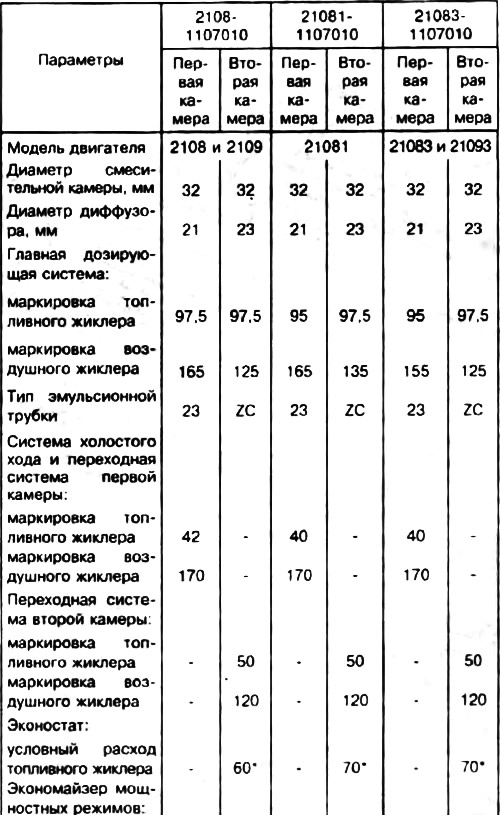
Pic. 14. Carburetor: 1. Carburetor heating block. 2 Throttle valve of the first chamber; 3. Branch pipe for suction of crankcase gases; 4 Accelerator pump drive lever; 5. Accelerator pump drive cam; 6. Accelerator pump diaphragm; 7. Fuel jet economizer power modes; 8. Pump housing; 9. Economizer diaphragm power modes; 10. Shut-off solenoid valve; 11 Idling fuel jet; 12. Carburetor cover; 13. The main air jet of the first chamber; 14. Air damper; 15. Accelerator pump nozzles with fuel supply valve; 16. Diaphragm of the starting device; 17 Trigger adjustment screw; 18. Adjusting screw for the amount of idle mixture; 19. Second chamber lock lever; 20. Branch pipe for supplying vacuum to the vacuum regulator of the ignition distributor; 21. Adjusting screw for the quality of the idle mixture; 22. Throttle control sector; 23. Throttle actuator lever; 24. Adjusting screw for slightly opening the throttle valve of the first chamber; 25. Choke control lever; 26. The rod of the starting device; 27. Electric wire of the economizer limit switch for forced idling; 28. Choke lever; 29. The main air jet of the second chamber; 30. Emulsion tube; 31. Atomizer of the main dosing system of the second chamber; 32. Fuel supply pipe; 33. Pipe for draining fuel into the tank; 34. Fuel filter; 35. Needle valve; 36. Throttle valve of the second chamber; 37. Throttle lever of the second chamber; 38. The main fuel jet of the second chamber; 39. Throttle actuator lever of the second chamber; 40. Float.
Emulsion-type carburetor with a falling flow, two-chamber with sequential opening of throttle valves. The carburetor has a balanced float chamber, heating of the throttle valve zone of the first chamber at the outlet of the fuel-air emulsion from the idle system, blocking of the second chamber when the air damper is not fully open.
The carburetor has two main dosing systems, a transition system and an idle system with an electromagnetic shut-off valve of the first chamber, a transition system of the second chamber, an econostat, an economizer of power modes, a diaphragm accelerator pump, a diaphragm starter. In addition, the electromagnetic shut-off valve 10 and the limit switch of the carburetor idle mixture adjusting screw 18, complete with an electronic control unit and electrical wires connecting them, constitute the forced idle economizer.
The carburetor is mounted on the intake pipe with four studs and fastened with nuts.
The blocking of the second chamber has a lever 19 with a pin and a spring mounted on the lever 23 of the throttle valve drive pivotally. If the air damper 14 is not fully open, the blocking prevents the opening of the throttle valve 36 of the second chamber, excluding the possibility of the second chamber being operated.
Throttle and air damper control drive cable. Throttle valves are opened by a pedal in the passenger compartment. The upper end of the pedal lever is connected by a cable to the throttle control sector 22. The cable is placed in a sheath.
The air damper 14 of the carburetor is controlled by a handle located under the instrument panel in the cabin. The handle is connected by a rod to the air damper control lever 25.
Note. The marking of the jets is determined by the flow rate, which is measured using micrometers. Adjustment of micrometers is carried out according to reference jets.
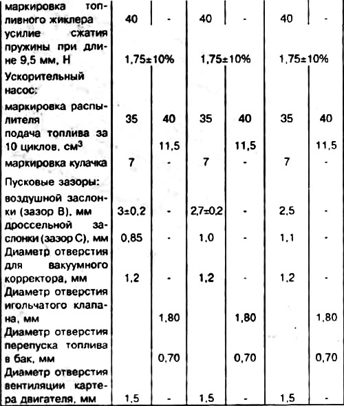
Calibration data for carburetors
* - the conditional consumption of fuel jets is determined by reference jets using a special method. They are not subject to control during operation.