




Contents: Removal ↓ Installation ↓
Removal
1. Place the vehicle on an inspection pit or overpass (see "Preparing a car for maintenance and repair").
2. Disconnect the wire from the negative terminal of the battery (see "Battery - Removal and Installation").
3. On a car with a 2107 instrument panel, remove the radio panel (see "Radio panel model 2107 - removal and installation").
[The original can be found on the website: www.VazBook.ru]
4. On a vehicle with a model 2105 instrument panel, remove the decorative cover of the gear shift lever from the ring of the mounting clip to the floor trim and slide the cover up the lever.
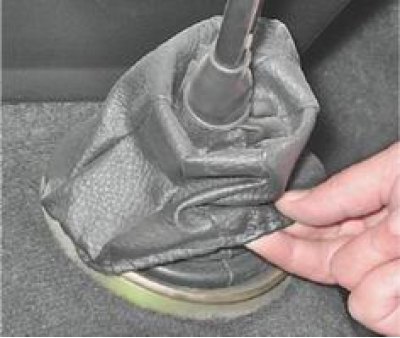
5. Carefully, using a screwdriver to pry around the perimeter, separate the rings of the clip.
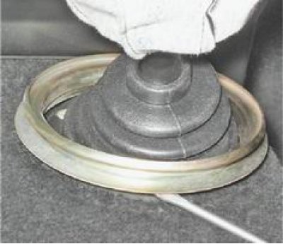
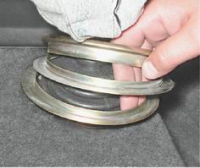
6. Remove the three rings that make up the clip from the floor tunnel trim.
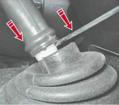
7. Pressing the lever, insert a screwdriver into the opening of the locking sleeve and, moving it down, remove the locking sleeve from the cavity of the rod. Remove the rod from the lever.
8. Using tweezers, remove the elastic rubber bushing of the lever damper from the lever rod.
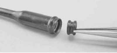
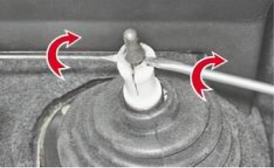
9. Using two screwdrivers, loosen the petals of the damper spacer sleeve and remove them from the groove of the lever.
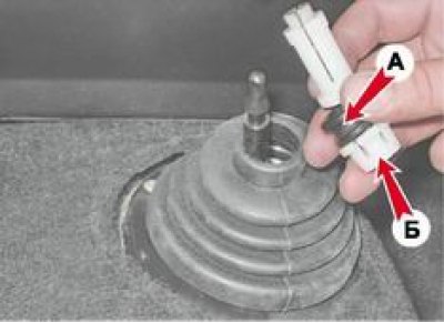
10. Remove the damper distance bushing, the lower rubber A and the locking B bushings from the lever.
11. By moving the floor trim, use a Phillips screwdriver to unscrew the four screws securing the cover that covers the opening in the body floor.
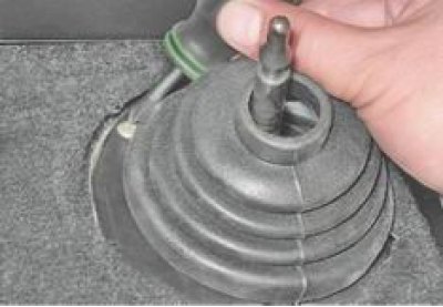
12. Remove the cover from the lever together with the foam seal.
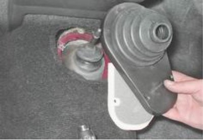
13. Remove the exhaust pipe (see "Intake pipe - removal and installation").
14. Disconnect the starter from the clutch housing and move it forward (see "Starter - removal and installation").
15. Disconnect the wiring harness from the reversing light switch (see "Reverse Light Switch - Checking and Replacing").
16. Remove the cardan transmission (see "Cardan transmission - removal and installation").
17. Disconnect the cross member of the rear support of the power unit from the body (see "Cardan transmission - disassembly and assembly").
18. Disconnect the flexible shaft from the speedometer drive (see "Speedometer Drive - Replacement").
19. Disconnect the clutch release hydraulic drive slave cylinder from the gearbox housing without disconnecting the hose from it (see "Clutch release hydraulic drive slave cylinder - removal and installation").
20. With a socket wrench by 10 mm we turn away two (on early production cars four) clutch housing cover mounting bolt.
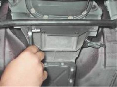
21. Install a reliable support under the gearbox. Using a socket wrench by 19 mm using an extension and a cardan joint, unscrew the four bolts securing the clutch housing to the cylinder block.
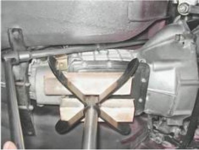
22. Insert a screwdriver into the gap between the clutch housing and the cylinder block, press the clutch housing away from the block and remove the housing from the guide bushings.
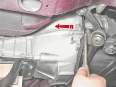
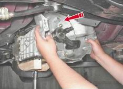
23. By moving the gearbox back, we remove the primary shaft from the hub of the driven clutch disk and simultaneously from the inner ring of the bearing located at the end of the crankshaft. Having released the shaft, we remove the gearbox.
Caution! Do not rest the gearbox with the end of the input shaft on the thrust flange of the clutch basket.
Installation
1. Before installation, clean the splined end of the primary shaft and apply a thin layer of SHRUS-4 grease to it.
2. Installation of all removed parts is performed in reverse order.