




The front wheel brake mechanism is disc. It consists of the parts shown in fig. 200 and Fig. 201 of the caliper 12 (4)* assembled with the working cylinders, brake disc 18, two brake pads 16 (11), connecting pins 8 (8) with springs (10) and pipelines.
* In brackets are references to positions in Fig. 201.
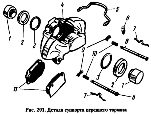
The caliper is attached to the bracket 11 with two bolts 9, which are locked by bending the locking plates to the edge of the bolts. The bracket 11 in turn is attached to the flange of the pivot pin 10 together with the protective casing 13 and the pivot lever. A groove is made in the caliper, through which the brake disk 18 passes, and two transverse grooves for placing the brake shoes 16. In the caliper lugs there are two windows with guide grooves, in which two opposite cylinders 17 are installed. To fix the cylinder relative to the caliper, a spring retainer 4 is installed in the cylinder, entering the side groove of the caliper. In each cylinder there is a hollow piston 3 (1), which is sealed with a rubber ring 6 (3). It is located in the groove of the cylinder and tightly compresses the surface of the piston. The cylinder cavity is protected from contamination by a rubber cap 7 (2). The working cavities of the cylinders are connected to each other by a tube 2 (5). A nipple 1 (6) for bleeding the front brake drive circuit is screwed into the outer cylinder, and a hose nipple for supplying fluid is screwed into the inner cylinder.
Piston 3 rests against brake shoes 16, onto which friction linings 5 are glued. The shoes are mounted on pins 8 and pressed against them by springs 15 (7). Pins 8 are held in the cylinder by cotter pins 14 (9). Brake disc 18 is secured to the wheel hub by two mounting pins.
When braking, the pistons under fluid pressure move out of the wheel cylinders and press the brake shoes to the brake disc. When moving, the pistons drag the sealing rings 6 along with them, which twist. When releasing the brakes, when the pressure in the drive drops, the pistons move back into the cylinders due to the elastic deformation of the rings. In this case, the linings 5 will be in light contact with the disc 18.
When the linings wear out and the gap in the brake mechanism increases, the pistons, under fluid pressure, slide relative to the rings 6 and take a new position in the cylinders, which ensures an optimal gap between the pads and the disc.