
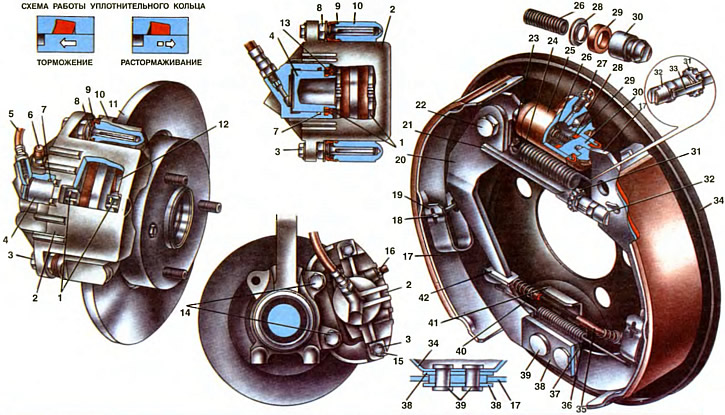
1. Front brake pads. 2. Caliper with cylinder. 3. A bolt of fastening of a support to directing fingers. 4. Piston. 5. Brake hose. 6. Cap of the fitting for pumping the brake drive. 7. Piston sealing ring. 8. Guide pin. 9. Protective finger cover. 10. Shoe guide. 11. Disc brake. 12. Pad clamping spring. 13. Piston protective cover. 14. Bolts of fastening of the brake mechanism to a rotary fist. 15. Locking plate. 16. Fitting for pumping the brake drive. 17. Block of the back brake mechanism. 18. Spring stand. 19. Shoe spring. 20. Lever for manual drive of brake pads. 21. Expanding bar. 22. Bolt of fastening of the lever. 23. Spring hook. 24. Top coupling spring pads. 25. Wheel cylinder. 26. Spacer spring pistons. 27. Fitting for bleeding the rear wheel brake drive. 28. Spring support cup. 29. Piston seal. 30. Piston. 31. Adjusting nut. 32. Movable pad stop. 33. Spring retainer. 34. Shield of the brake mechanism. 35. Parking brake cable. 36. Lower coupling spring pads. 37. Support plate pads. 38. Pad guide plate. 39. Rivets. 40. Rope return spring. 41. Cable guide plate. 42. The tip of the cable.
The brake mechanisms of the wheels under the action of the force from the hydraulic drive create and change the braking torque on the wheels. This is achieved by pressing against rotating discs (drums) fixed brake pads. The resulting friction forces create a braking torque on the wheels, the magnitude of which depends on the force on the brake pedal and the drive of its movement.
Two types of brake mechanisms are used on the car: on the front wheels - disc, on the rear - drum.
Front wheel brake
Brake mechanism of the front wheel with automatic adjustment of the gap between the pads and the disc, with «floating» bracket. brace (caliper) 2 is cast from aluminum alloy together with the wheel cylinder. It is fastened with two bolts 3 to the guide pins 8, which are installed in the holes of the guide 10 of the blocks. To protect the fingers from corrosion, UNIOL-1 grease is put into the holes of the guide during assembly. This ensures the required movement of the bracket, regardless of the age of the vehicle. The surface of the fingers is protected from the impact of aggressive environments by rubber covers 9. Their edges go into the annular grooves of the guide pads and fingers. To prevent air resistance from being created in the holes of the guide when moving the fingers due to its compression, flats are made on the pin shaft. Mounting bolts «floating brace» are locked by bending the locking plates 15 on the verge of the bolts.
The shoe guide is attached with two bolts 14 to the steering knuckle. In the groove of the guide 10 there are two brake pads 1, between which there is a disc 11 of the brake. The pads are pressed against the grooves of the guide by leaf springs 12. They are put on the stepped protrusions of the pads, and their ends rest against the shelves of the caliper grooves. The caliper has a window for inspecting the brake pads.
A hollow piston 4 with a sealing ring 7 is installed in the cylinder cavity. Due to the elasticity of this ring and a groove of a special configuration, a certain gap between the pads and the disk is maintained in the cylinder. The sealing ring tightly covers the piston, and during its course it twists, and when released, it unwinds and returns the piston to its original position. The cylinder cavity is protected by a rubber boot 13, the edges of which cover the piston and cylinder. Two holes are made in the cylinder - a hose fitting 5 for supplying brake fluid is screwed into one, and a fitting 16 is screwed into the other for bleeding the brake actuator.
Brake pads are steel, have a figured shape, which ensures their tight fit to the guide pads. In the upper part of the pad there is a protrusion on which the leaf spring 12 is put on. When installing the pads, the ends of the springs abut against the shelves of the caliper grooves, which ensures that the pads are constantly pressed against the grooves of the guide. Thus, a tight fit of the pads is created, which eliminates their vibration. Friction pads are glued to the pads, the working surface of which is polished.
Brake disc 11 is made of cast iron. Four holes are made in the disc hub, one with a thread, for fastening the brake disc to the wheel hub with a bolt, the rest - for the passage of bolts for fastening the wheel disc. The working surface of the disc is made with high precision. Cracks, shells and deep risks are not allowed on it. The normal thickness of the disc is 9 mm, the maximum allowable is 7.8 mm.
Rear wheel brake
The brake mechanism of a back wheel drum with manual adjustment of a backlash between pads and a drum. It is mounted on a support plate 34, which is attached to the rear suspension arm flange along with the rear wheel axle. At the bottom of the shield, two rivets 39 fasten a package of plates, one of which is a support (pos 37) for brake pads, other plates (pos 38) direct the movement of the lower part of the shoes on the base plate, limiting their axial movement.
In the upper part of the shield, a wheel cylinder 25 is fastened with two bolts.
The brake pads are pulled together by the upper 24 and lower 36 springs, which press the pads to the lower support and to the stops of the pistons 30 of the wheel cylinder. The block is kept from lateral displacement: in the lower part by the guide plates 38 of the support, in the upper part by the groove of the stops of the pistons 30 of the wheel cylinder, in the middle part by flat springs 19 put on the racks 18. brake drum. This improves braking performance and results in more even brake pad wear.
Two fittings are screwed into the threaded holes of the wheel cylinder, one (pos 27) - for bleeding the rear wheel brake drive, the other - for the supply hose.
On the edge of the rear pad, the lever 20 of the manual drive of the pads is hinged, with the help of a bolt 22. Between this lever and the rib of the front brake shoe, an expander bar 21 of adjustable length is installed. It consists of the bar itself, the stop 32 of the shoe and the adjusting nut 31 with a spring lock 33. The nut is screwed onto the threaded end of the bar and the stop 32 of the shoe rests against it, located at the end of the bar. The rib of the front brake shoe enters the slot of the stop. The adjusting nut has external teeth that can be used to turn the nut. This changes the length of the expansion bar, i.e. the gap between the shoes and the drum. To access the nut in the brake drum, a hole is made, closed with a rubber plug. The position of the nut is locked by a spring retainer 33. When the nut is turned, it is squeezed out of the cavity of the tooth, and then enters a new cavity.
In the future, on cars of the family «Oka» automatic adjustment of the gap between the shoes and the drum is provided.
The wheel cylinder 25 of the brake mechanism consists of a housing in which two pistons 30 with seals 29 and a spacer spring 26 with cups 28 are located. The cylinder cavity is sealed with rubber covers. The pumping of the brake mechanism drive is carried out through the fitting 27.
Brake drum 1 (see ch. 25) cast together with the rear wheel hub from ductile iron. To access the nut for manually adjusting the gap between the shoes and the drum, there is a hole with a diameter of 20 mm from the end of the drum. It is closed with a rubber plug 24. Bearing sockets are machined in the wheel hub, and three bolts are pressed into the holes of the hub, on which the wheel disks are mounted.
The nominal drum diameter is 180 mm, the maximum allowable diameter is 181.5 mm.