
Removing
Raise the front of the car, put it on stands and remove the wheel. Unscrew the fitting, disconnect the flexible hose from the line, plug the openings of the hose and steel tube to prevent leakage of brake fluid. Pulling out cotter pin 14 (see fig. 200), and then fingers 8 with springs 10 (see fig. 201), remove springs 15 (see fig. 200) and brake pads 16. Mark the pads so that they can be installed in their original places during assembly. Having straightened the locking plates, unscrew the two bolts 9 that secure the caliper to the bracket, and remove the caliper.
You can remove the brake (without brake disc) assembled with brake wells, for which disconnect the hose and unscrew the bolts 9 of the caliper.
Installation
It is carried out in reverse order. After that, restore the fluid level in the reservoir, bleed the brake drive.
Disassembly and assembly
Disconnect tube 5 (see fig. 201) and remove dust caps 2 from the cylinders. Then, blowing compressed air through the brake fluid inlet, push the pistons 1 out of the cylinders on the caliper 4 and remove the O-rings 3 from the cylinders.
With prolonged use of the car, corrosion of the working cylinders occurs. In this case, as well as in case of wear or damage to the working surfaces of the cylinder or piston, replace the cylinder assembly. To do this, after performing the above operations, clamp the caliper in a vice, drown the latches and knock out the cylinder from the grooves of the caliper with a rubber hammer. After that, install a new cylinder in the grooves.
Assemble the brake mechanism in reverse order. At the same time, lubricate the sealing rings, pistons and cylinder mirror with brake fluid.
Checking details
Check all parts by first washing them with warm water and detergent and drying them with compressed air. If the piston or cylinder bore shows signs of wear or seizing, replace the cylinder complete with pistons. In all cases, when the piston is removed from the cylinder, it is recommended to replace the O-ring in the cylinder grooves and the dust cap.
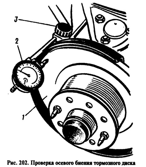
Checking brake disc runout
Axial runout of the brake disc 1 (pic. 202) check without removing it from the car. The largest allowable runout on indicator 2 is 0.15 mm. The indicator is installed using a magnetic stand 3. If the runout is greater, grind the disc using the mandrel 67.7141.9500. Then sand it, but the final thickness of the disc should not be less than 9.5 mm. In case of damage or very deep scratches, or wear exceeding 0.5 mm on each side, replace the disc with a new one.
Replace the disc only together with the front wheel hub, as its final processing is carried out in assembly with the hub. Removing and installing it with a brake disc is described in the section «Chassis».
Replacement of brake pads
Replace the pads with new ones if the thickness of the pads has decreased to 1.5 mm. To replace the pads, remove cotter pins 14 (see fig. 200) and fingers 8 with springs. Then remove pads 16 and springs 15. Carefully, so as not to damage the dust caps and prevent fluid from splashing out of the hydraulic drive reservoir, sink the pistons into the cylinders. Install new pads, then pins, springs and cotter pins, first applying a thin layer of some kind of grease to the surface of the pins.