




Open large image in new tab »
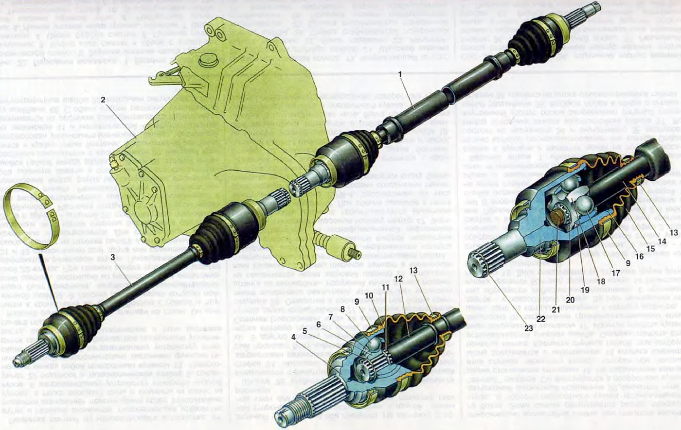
Figure 21. Front wheel drive: 1. Right front wheel drive; 2. Gearbox; 3 Left front wheel drive; 4. Outer hinge housing; 5. Hinge cage retaining ring; 6, 18. Hinge sleeve; 7, 19. Hinge separator; 8, 17 Ball joint; 9. Outer cover clamp; 10, 15. Protective cover of the hinge; 11. Thrust ring; 12, 14. Left wheel drive shaft; 13. Inner clamp of the cover; 16. Inner hinge lock; 20. Retaining ring of inner joint cage; 21. Shaft buffer; 22. Inner hinge housing; 23. Retaining ring of the axle gear.
A front-wheel drive vehicle is characterized primarily by the fact that the front steered wheels are also the driving wheels. To turn the driving wheels, ball joints are located on the shafts (semi-axles) of the drive, which must allow the wheels to turn without changing their rotation speed. This condition is satisfied by constant velocity cardans (synchronous ball joints). A conventional cardan joint quickly fails under these conditions, since deviations of its driving and driven links create an uneven angular velocity transfer of rotation to the driven link. This causes overload of the drive shafts and rapid wear of the cardan joint.
Modern front-wheel drive vehicles use semi-axles with two synchronous ball joints to drive the front wheels: the drive wheel is of a rigid type (with angular degree of freedom), and the power unit is of a universal type (with angular and axial degrees of freedom).
The front wheel drive used in the car is compact and reliable. Its durability is high when the car is used correctly. This is ensured by the perfection of the hinge design, the selection of improved materials, the precision of the parts, good sealing of the hinges and the use of special grease.
The drives of the right 1 and left 3 wheels have the same design and differ in shafts, which are solid for the left wheel drive and tubular for the right, and in length. The latter is explained by the shift of the gearbox to the left side of the vehicle's axis.
The drive of each wheel consists of two cardan joints of equal angular velocities and a shaft. The outer joint, connected to the wheel hub, consists of a housing 13, a separator 6, an inner race 4 and six balls. In the joint housing and in the race there are radial rolling tracks, the curvature of which has a meridional direction. In these tracks there are balls connecting the housing 4 and the inner race 6. The balls are placed in the windows of the separator 7 and are held by it in one plane. As a result, the inner race and the joint housing are centered. The working angle of rotation of the outer joint is up to 42°.
The inner race is mounted on the splines of shaft 8 until it stops against ring 11. The race is held on the splines of the shaft by retaining ring 5. The separator has a spherical surface and windows for balls. It ensures synchronicity of rotation of the shafts connected by the hinge by installing balls in a sector-free plane of the angle of the intersecting axes of the hinge links, i.e. it acts as a divider. As a result, regardless of the angle of rotation of the hinge, the balls are always held in the plane of constant rotation frequency. At the same time, torque is transmitted through the separator.
To seal the cavity of the hinge, a corrugated rubber cover 10 is used, which is fastened to the hinge housing and to the shaft 12 of the wheel drive with clamps 9 and 13. The tightness of the places of the cover fit is ensured by annular grooves on the hinge housing, into which the cover is pressed when tightening the clamp. On the other side, grooves are made in the cover itself, they create a labyrinth seal. Axial fixation of the cover on the shaft is achieved by thrust flanges on the drive shaft. The tightening clamps are made of steel tape, on which three nests and one locking tooth are stamped. Two nests serve to tighten the clamp with a special device, the locking tooth goes into the third. The hub of the front wheel is mounted on the splined tip of the hinge housing. It is fastened with a self-locking nut.
The inner joint is connected to the differential axle gear. It has minor design differences compared to the outer joint. This is primarily due to the fact that the tracks in the joint housing and in the collar are made straight, not radial, which allows the joint parts to move in the longitudinal direction. This is necessary to compensate for movements caused by vibrations of the front suspension and the power unit. The longitudinal movement of the collar in the joint housing is limited on one side by a wire retainer 16, on the other - by a plastic buffer 18. The retainer is installed in the groove of the joint housing, and the buffer in the end of the wheel drive shaft. The tail of the joint housing is connected by splines to the differential axle gear. The axle gear is held on the shaft splines by a locking ring 23.
Protection of the hinge parts from moisture and dirt is carried out in the same way as for the outer hinge.
When assembling cardan joints, special SHRUS-4 grease is added to them. During vehicle operation, grease is not replaced if the covers ensure the tightness of the joints.
Front wheel drives operate under the most severe and unfavorable conditions, as they are located in the zone of greatest impact of moisture and dirt and transmit torque to the wheels under constantly changing angles and loads. High precision manufacturing of hinge parts, use of high-quality materials and lubricants ensure reliable operation of the unit in these conditions, but only if the hinges are kept tight. Therefore, it is necessary to periodically check the condition of the protective covers and clamps in order to promptly detect cracks, deformations or traces of contact with the road surface and take measures to replace them. This prevents premature wear of the hinges.