
Health check
To check, place the car on a lift or inspection hole and clean the pressure regulator and protective cover from dirt. Carefully remove the protective cover from the pressure regulator, remove any remaining grease and clean the torsion-piston connection. Press the brake pedal with a force of 70-80 kgf and at the same time observe the protruding part of the pressure regulator piston. If the piston moves relative to the pressure regulator housing by 0.5-0.9 mm, while twisting the torsion lever, then the pressure regulator is operational. Continue depressing the pedal 2-3 times to fully verify that the pressure regulator is working. If the piston remains stationary when the pedal is depressed, indicating corrosion between the piston and housing, replace the pressure regulator with a new one.
After making sure that the pressure regulator is working and that there is no fluid leakage between the piston and the regulator body, apply a layer of DT-1 grease on the axis and protruding part of the piston and, placing 5-6 g of the same grease in a rubber boot, install it.
Removal and installation
Disconnect lever 4 (pic. 197) from the rod 7, and then the bracket 5 from the body and the bracket for fastening the pipelines going to the body 3 of the regulator. Disconnect the muffler suspension parts from the body and take the pipeline with the mufflers to the side.
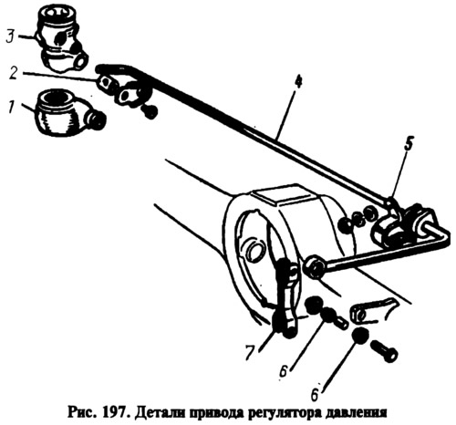
Turn away bolts of fastening of a regulator to an arm and an arm to a body, remove an arm of fastening of a regulator, and then lower a regulator down, disconnect the drive lever from it. Plug pressure regulator openings and lines.
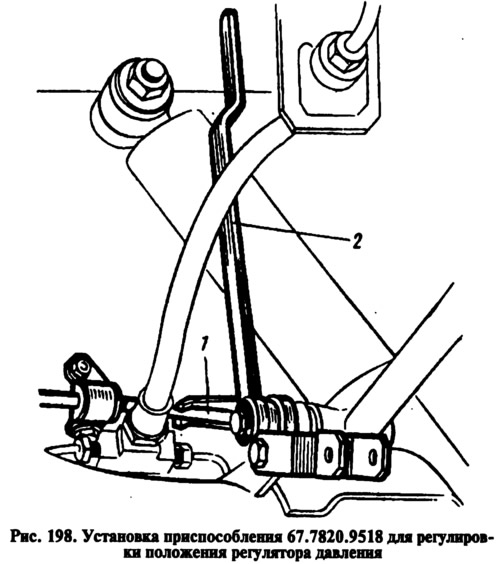
Install the pressure regulator in the reverse order with the rear axle of the car suspended. Before tightening the pressure regulator mounting bolts, install tool 67.7820.9518 2 at the end of the drive lever 1 (pic. 198). The rod of the device is directed upwards until it stops in the body. This sets the distance of 140±5 mm between the end of the lever 1 and the side member of the body.
Lift the protective cap 1 (see fig. 197) and, turning the pressure regulator on the mounting bolts, ensure that the end of the lever is in light contact with the regulator piston. While holding the regulator in this position, tighten the bolts of its fastening to failure, then cover the axis 2 and the protruding part of the piston with a layer of grease DT-1. Reinstall the protective cap 1, filling it with 5-6 g of the same lubricant.
Remove fixture 67.7820.9518 and connect the end of the lever with the rod, having previously lubricated the bushings 6 of the hinged connection of the rod with the lever with DT-1 grease. Attach the pipes of the exhaust system to the body. Bleed the brakes to remove air from the rear brake actuator.
Disassembly and assembly
Removing the plug 6 (see fig. 196) from body 4, remove gasket 5, take out piston 10, spacer sleeve 3, seal 7, plate 8, spring 9 and thrust washer with sealing ring 2. When assembling, lubricate all parts with brake fluid and install in reverse order.
Checking details
Flush the parts with brake fluid and inspect. The surfaces of the parts should not have visible scratches and irregularities. Replace damaged parts, as well as the seal and the sealing ring. Check the elasticity of the spring, while its length in the free state should be 17.8 mm, and under load 7+0,8-0,4 kgf - 9 mm.