
Pressure regulator 20 (see fig. 170) mounted on the body bracket and connected to the rear axle beam through the torsion lever 23 and rod 13. The other end of the lever 23 acts on the piston 10 (pic. 196).
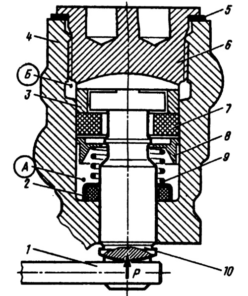
Pic. 196. Rear brake pressure regulator (in working position):
1 - lever; 2 - thrust washer with sealing ring; 3 - spacer sleeve; 4 - body; 5 - gasket; 6 - cork; 7 - sealant; 8 - plate; 9 - spring; 10 - piston.
Fluid enters cavity A from the master cylinder, and from cavity B it exits into the wheel cylinders of the rear brake drive. The force P acting on the piston from the torsion lever increases as the body approaches the axle beam and decreases as the body moves away from the rear axle beam.
Prior to the start of the regulator action, the piston 10 rests against the plug 6 under the action of the force P and the spring 9. In this case, gaps are formed through which the cavities A and B communicate, i.e. the pressure in them will be the same and equal to the pressure in the brake hydraulic drive. When the brakes are applied, the rear of the car rises by inertia and, consequently, the pressure on the piston from lever 1 decreases. The force of fluid pressure on the upper end of the piston, which has a large surface area, will at some point exceed the fluid pressure force acting on the piston from below, and the piston will go down until it stops in seal 7. Cavities A and B are separated and different pressures are created in them: in cavity A, pressure PA will be equal to the pressure in the main cylinder, and in cavity B the pressure PB will be less than RA by a value that determines the equilibrium of the piston under pressure PA and RB, spring 9 and the force of the torsion lever. Thus, partial or complete separation of cavities A and B by piston 10 regulates the amount of braking torque on the rear wheels.