

Open large image in new tab »
Pic. 4: 1. Connecting rod cap. 2. Connecting rod bushing. 3. Connecting rod. 4. Starter. 5. Heat shield starter. 6. Exhaust manifold. 7. Inlet pipe. 8. Inlet pipe drain tube. 9. Pipe fitting for draining coolant. 10. Outer valve spring. 11. Internal valve spring. 12. valve cotter. 13. Spring plate. 14. Oil cap. 15. Valve drive lever. 16. Valve lever spring. 17. Valve adjusting bolt. 18. Adjusting bolt locknut. 19. Ignition distributor. 20. Valve lever spring retainer plate. 21. Bushing of the adjusting bolt. 22. Valve guide. 23. Valve seat. 24. Piston. 25. Eccentric for driving the fuel pump. 26. Oil pump drive shaft and ignition distributor. 27. Gear drive oil pump and ignition distributor. 28. Fuel pump. 29. Oil filter. 30. Fitting for fastening the oil filter adapter. 31. Oil filter adapter. 32. Gasket. 33. Oil pump roller. 34. The axis of the driven gear of the oil pump. 35. Oil pump housing. 36. Oil pump drive gear. 37. Pressure reducing valve spring. 38. Oil pump pressure reducing valve. 39. oil pump cover. 40. Oil pump driven gear. 41. Oil pump inlet pipe. 42. Alignment mark on the camshaft pulley. 43. Mounting protrusion on the camshaft bearing housing. 44. Camshaft pulley. 45. Tension roller. 46. Tension roller bracket. 47. Tension spring. 48. Camshaft timing belt. 49. Pulley drive oil pump and ignition distributor. 50. Alignment marks on the camshaft cover. 51. Toothed pulley of the crankshaft. 52. Alignment mark on the toothed pulley. 53. Mark w.m.t. crankshaft pulley. 54. Ignition advance mark by 55. Ignition advance mark by 5°. 56. Ignition advance mark by 10. o7. Oil ring. 58. Lower compression ring. 59. Top compression ring.
The regulation of the processes of inlet of the fuel mixture into the cylinders and the release of exhaust gases from them in accordance with the order of operation of the cylinders and the valve timing adopted for the engine, is carried out by the gas distribution mechanism, which is driven from the drive pulley 51 of the crankshaft by a toothed belt 48. The same belt through the pulley 49 the oil pump, ignition distributor and fuel pump are actuated. The belt drive operates in a dry environment without lubrication.
A feature of the drive is the use of a belt drive with a toothed belt. The belt is made of rubber and reinforced with a spiral wound fiberglass cord for high strength. The teeth of the belt are trapezoidal and covered with an elastic fabric to increase wear resistance. The rubber, cord and fabric sheath of the teeth are vulcanized into a single strong element capable of withstanding a tensile load of up to 10,000 N (1000 kgf).
The belt tension is adjusted using the tension roller 45, mounted on the bracket 46. The degree of belt tension is set by the spring 47 on the idle engine with the bolts of the tension roller bracket loosened. Outside, the belt drive is closed with three plastic protective covers.
In the left front part of the cylinder block, a shaft 26 for driving the oil pump, ignition distributor and fuel pump is installed. The roller is installed along the engine and has two support journals, a helical gear and an eccentric 25, which drives the fuel pump through the pusher. Collapsed steel-aluminum bushings 50 are pressed into the holes for the roller bearings (see fig. 3). Since 1984, the rear hub has been made of sintered metal. The joint processing of the bushings in the block ensures the necessary alignment of the bearings. For the passage of oil, the front bushing has a hole located against the lubrication channel in the cylinder block. When checking the technical condition of the block and repair, it is necessary to monitor the coincidence of the lubrication hole in the front bush with the channel in the cylinder block.
The roller is cast iron, the surface of the eccentric is hardened by high-frequency currents to a depth of 2±0.5 mm. Along the axis of the roller there is a hole for supplying oil from its front support to the rear. The gaps between the bushings and the bearing journals of the oil pump drive shaft and the ignition distributor must correspond to 0.046-0.091 mm for the front support, and 0.040-0.080 mm for the rear; the maximum allowable clearance for both supports is 0.15 mm.
Roller helical gear 26 meshes with gear 27 which drives the ignition distributor and oil pump. Gear 27 is installed vertically and rotates in a ceramic-metal bushing pressed into the cylinder block. The gear has a slotted hole, which includes the splined ends of the rollers of the ignition distributor and the oil pump. The ignition distributor housing is mounted on the upper plane of the cylinder block and is attached to it with a steel plate. The oil pump is bolted to the bottom plane of the cylinder block.
Engine operation
In one working cycle in the engine cylinder, there are four strokes of the intake of a combustible mixture, compression, power stroke and exhaust gases. These cycles are carried out in two revolutions of the crankshaft, i.e. each beat occurs in half a turn (180°) crankshaft.
The inlet valve starts to open ahead of time, i.e. until the piston reaches top dead center (V. m. t.) to a distance corresponding to 12°of rotation of the crankshaft to c. m. t. This is necessary so that the valve is fully open when the piston goes down, and as much fresh combustible mixture as possible enters through the fully open inlet.
The inlet valve closes with a delay, i.e. after the piston has passed bottom dead center (n. m. t.) at a distance corresponding to 40°rotation of the crankshaft after n. m. t. Due to the inertial pressure of the jet of the combustible mixture being sucked in, it continues to flow into the cylinder when the piston has already begun to move upward, and thus the best filling of the cylinder is ensured. Thus, the intake practically occurs during the rotation of the crankshaft by 232°.
The exhaust valve begins to open even before the full end of the working stroke, before the piston approaches n. m. t. at a distance corresponding to 42°of rotation of the crankshaft BC. m. t. At this moment, the pressure in the cylinder is still quite high, and the gases begin to intensively flow out of the cylinder, as a result of which their pressure and temperature drop rapidly. This significantly reduces engine work during exhaust and prevents the engine from overheating.
The release continues after the piston has passed through. m.t., i.e. when the crankshaft rotates 10°after c. m. t. Thus, the duration of the release is 232°.
There is such a moment (22°crankshaft rotation approx. m. t.), when both intake and exhaust valves are open at the same time. This position is called valve overlap. Due to the short time interval, the overlapping of the valves does not lead to the penetration of exhaust gases into the intake manifold, but, on the contrary, the inertia of the exhaust gas flow causes the combustible mixture to be sucked into the cylinder and thereby improves its filling.
The described valve timings take place with a gap of 0.30 mm between the camshaft cam and the valve actuation lever on a cold engine.
To ensure the timing of the opening and closing of the valves with the angles of rotation of the crankshaft (those. ensure the correct installation of the valve timing), on the crankshaft and camshaft sprockets there are marks 52 and 42, as well as 50 on the camshaft drive cover and 43 (ledge) on the camshaft bearing housing. If the valve timing is set correctly, then when the piston of the fourth cylinder is in c. m.t. at the end of the compression stroke, mark 43 on the camshaft bearing housing must match mark 42 on the camshaft sprocket, and mark 52 on the crankshaft sprocket with a vertical mark 50 on the camshaft drive cover.
When the camshaft drive cavity is closed with protective covers, the position of the crankshaft can be determined by the marks on the crankshaft pulley and the middle protective cover of the camshaft drive. With the piston position of the fourth cylinder in c. m.t. mark 53 on the pulley must match mark 54 on the middle protective cover of the camshaft drive.
To ensure normal engine operation, the clearances between the cams and valve actuator levers are set to 0.15 mm on a cold engine. These gaps are necessary in order to ensure the correct operation of the gas distribution mechanism during the thermal expansion of parts on a running engine. The deviation of the gaps for various valves on one engine should not exceed 0.02-0.03 mm.
If the gaps differ from the specified value, then the valve timing is distorted: with an increased gap, the valves open with a delay and close ahead, and with an insufficient gap, they open ahead and close with a delay. If there is no gap, then the valves remain slightly ajar all the time, which drastically reduces the life of the valves and seats.
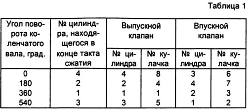
The gaps between the cams and the valve levers are set as follows: by turning the crankshaft clockwise until mark 42 on the camshaft pulley matches mark 43 on the bearing housing, which corresponds to the end of the compression stroke in the fourth cylinder, set the gap at the exhaust valve of the fourth cylinder (eighth cam) and inlet valve of the third cylinder (sixth cam). Then, successively turning the crankshaft by 180°, set the clearances for the valves of the remaining cylinders in the order indicated in Table 1.
To set the required clearance, you should: holding the adjusting bolt 17 of the lever with a wrench, loosen the lock nut of the bolt with another wrench, insert a probe 0.15 mm thick between the lever and the camshaft cam and use a wrench to wrap or unscrew the adjusting bolt 17, followed by tightening the lock nut until locknut, the feeler gauge will not go in with a slight pinch.