
Wiring diagram of the generator on the test stand
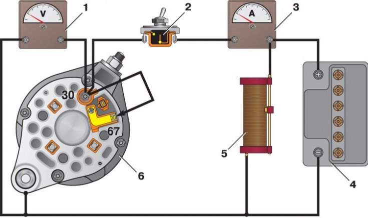
1 - voltmeter; 2 - switch; 3 - ammeter; 4 - storage battery; 5 - rheostat; 6 - generator
Testing on the bench allows you to determine the health of the generator and the compliance of its characteristics with the nominal ones. For the generator under test, the brushes must be well ground to the slip rings of the collector, and the rings themselves must be clean.
1. Install the generator on the stand and make connections as shown in fig. Wiring diagram of the generator on the stand for testing.
2. Turn on the electric motor of the stand, set the generator output voltage to 14 V with rheostat 5 and bring the rotor speed to 5000 min–1. Let the generator run in this mode for at least 2 minutes, and then measure the recoil current. For a working generator, it must be at least 44 A.
3. If the measured value of the output current is much less, then this indicates a malfunction in the stator and rotor windings, damage to the valves or wear of slip rings and brushes. In this case, a thorough inspection of the windings and valves is necessary to determine the location of the fault.
4. If you suspect a malfunction of the generator rectifier unit valves, check the output current on a warm generator. Such a check allows you to better identify the malfunction of the valves by a sharp decrease in the recoil current with an increase in the temperature of the generator.
5. To warm up, let the generator run for at least 15 minutes at a rotor speed of 5000 minutes–1 and a voltage of 14 V at the output of the generator. Then measure the recoil current. On a warm generator, it should be at least 42 A.