




Cylinder block
Cast iron, cast. Block cylinders are divided into 5 classes by diameter (through 0.01 mm). Cylinder class (latin letter) is stamped on the lower plane of the block opposite each cylinder. It is possible to bore the cylinders for repair pistons.
The crankshaft main bearing caps are machined together with the cylinder block, so they are not interchangeable and have marks on the outer surface to differentiate them (see figure 30). The main bearing caps are attached to the block with self-locking bolts, which cannot be replaced with any other ones.
Piston
Cast from aluminum alloy. During manufacturing, the piston weight is strictly maintained, so when assembling the engine, it is not necessary to select pistons of the same group by weight.
According to the outer diameter, pistons are divided into five classes (4, B, C, D, E) through 0.01 mm. The outer surface of the piston has a complex shape: it is conical in height and oval in cross section. Therefore, it is necessary to measure the piston diameter only in the plane perpendicular to the piston pin, at a distance of 51.5 mm from the piston bottom.
According to the diameter of the hole under the piston pin, pistons are divided into three classes (1, 2, 3) through 0.004 mm. Piston diameter classes 3 (figure 4) and the holes for the piston pin 4 are stamped on the bottom of the piston.
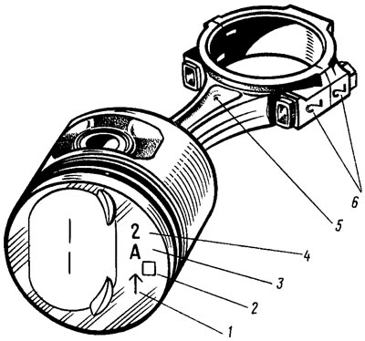
Figure 4. Piston and connecting rod markings
Pistons of repair sizes are manufactured with an outer diameter increased by 0.4 and 0.8 mm. The bottoms of these pistons are marked with a triangle or square 2. The triangle corresponds to an increase in the outer diameter by 0.4 mm, and the square - by 0.8 mm.
Arrow 1 on the piston bottom shows how to correctly orient the piston when installing it in the cylinder. It should be directed towards the camshaft drive, just like hole 5 on the connecting rod for oil outlet.
The piston rings are made of cast iron. The upper compression ring has a chromed outer surface. The lower compression ring is of the scraper type. The oil scraper ring has chromed working edges and a spiral expansion spring.
Piston pin
Steel, pressed into the upper head of the connecting rod and rotates freely in the piston bosses. According to the outer diameter, the pins are divided into three classes through 0.004 mm. The class is marked with paint on the end of the pin: blue mark - 1st class, green - 2nd, and red - 3rd class.
Connecting rod
Steel, processed together with the cover and therefore they are not interchangeable separately. In order not to mix up the covers and connecting rods during assembly, they are stamped with the number 6 of the cylinder in which they are installed.
Crankshaft
Cast, cast iron, 5-bearing. It is possible to regrind the crankshaft journals during repairs with a diameter reduction of 0.25 mm; 0,5; 0.75 and 1 mm.
The axial movement of the crankshaft is limited by two steel-aluminum thrust half rings. They are inserted into the cylinder block sockets on both sides of the central main bearing. The half rings are manufactured in two sizes - normal and increased by 0.127 mm.
Crankshaft bearing liners are thin-walled, steel-aluminum. Main bearing liners with a groove on the inner surface, connecting rod liners without a groove. Repair liners are made with increased thickness for crankshaft journals, reduced by 0.25 mm; 0,5; 0.75 and 1 mm.
Flywheel
Cast iron, cast, with a pressed steel toothed ring for starting the engine with a starter. The flywheel is centered by a cylindrical protrusion on the crankshaft flange. On the rear plane of the flywheel near the toothed ring there is a setting mark in the form of a conical hole. It should be opposite the crank pin of the 4th cylinder. The flywheel is balanced separately from the crankshaft.