




Hood
Hood (figure 144) consists of external and internal panels made of 0.8 mm thick sheet steel. The panels are connected to each other by bending the flanges with glue. Expanding gaskets are installed between the panels.
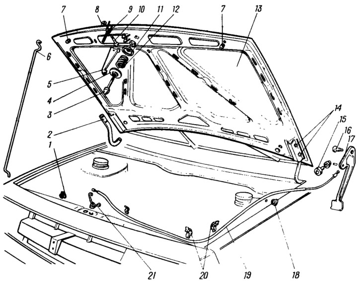
Figure 144. Hood and lock parts:
1 - hood stop bushing; 2 - hood hinge; 3 - pin; 4 - lower cup; 5 - hook; 6 - stop: 7 - buffers; 8 - lock washer; 9 - hook spring; 10 - hook axis, 11 - upper cup; 12 - pin spring; 13 - hood; 14 - hood mounting bolt, 15 - rod casing bushing; 16 - handle axis; 17 - handle; 18 - Lock rod seal; 19 - shell with lock rod; 20 - Lock rod holders; 21 - lock spring.
The hood is hung on hinges 2 along the rear edge, in front it rests on rubber buffers 7. In the front part of the hood and the front of the body, a lock with a hook 5 is installed, preventing the spontaneous opening of the hood. The hook is pressed by a spring 9. The lock drive is cable, the handle 17 of the lock is located in the passenger compartment on the left side under the instrument panel. The handle is connected by a rod in a casing 19 to a spring 21, fixing the hood by pin 3 in the closed position. The pin is screwed into the hood and locked with a lock nut. By changing the position of pin 3 by height, the position of the hood is adjusted in relation to the front surfaces of the front wings and the radiator grille. Cups 4 and 11 with a spring between them are installed on the pin. In the open position, the hood is held by a metal stop 6. The end of the stop is installed in a plastic bushing.
The enlarged holes in the brackets for fastening the hinges on the hood allow the adjustment of the hood position in the body opening. When adjusting, loosen the bolts 14 fastening the hinges, move the hood to the desired position so that the gaps between it and the front fenders are the same, and tighten the bolts.
If the hood is not securely locked, loosen the lock nut securing pin 3 and move it by means of the enlarged hole in the hood, achieving alignment with the lock socket. After completing the adjustment, tighten the lock nut.
Bumpers
The body is covered in front and back by energy-intensive bumpers. Each of them consists of an aluminum beam 4 (figure 145), 1 trim and brackets for attaching the bumper to the body. The bumper trim is made of black microporous polyurethane foam with the addition of 15% crushed fiberglass and is attached to an aluminum beam. The front bumper is attached to the body frame using the front 6 and side 2 brackets.
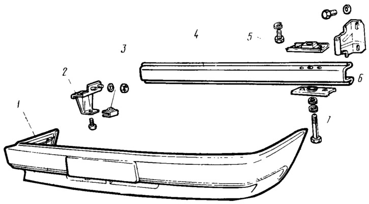
Figure 145. Bumper details:
1 - bumper trim; 2 - side bracket; 3 - bracket; 4 - aluminum beam; 5 - mounting strips; 6 - front bracket.
Original source is on the resource VAZBOOK.RU
The rear bumper is also attached to the body using side and rear brackets.
Radiator lining
Radiator lining (figure 146) is made, like the bumper, from microporous polyurethane foam with the addition of 20% crushed fiberglass. The grille 3 of the radiator with the factory sign installed on it is attached to the lining 6 in front using hooks and the metal reinforcement 7 is attached to the rear edge using nuts. The lining and the grille are covered with polyurethane enamel to match the color of the body.
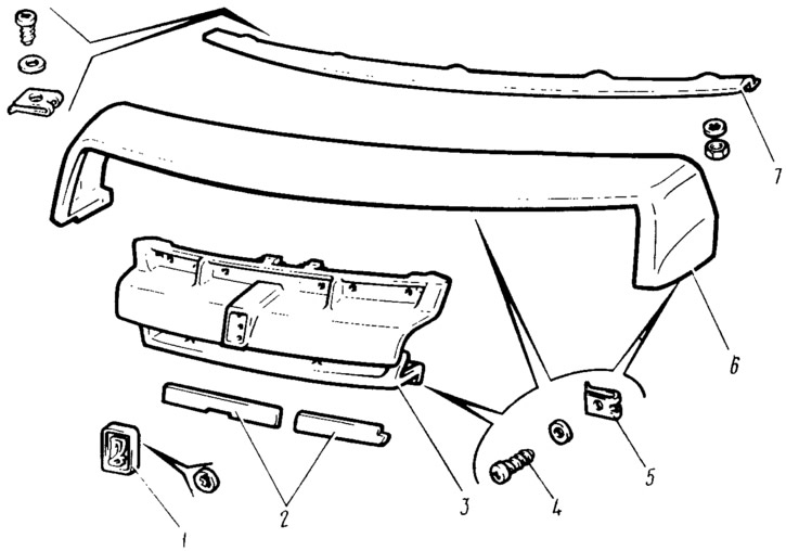
Figure 146. Radiator trim parts:
1 - factory mark; 2 - radiator grille trims; 3 - radiator grille; 4 - self-tapping screw; 5 - screw bracket; 6 - radiator trim; 7 - lining reinforcement.
The trim assembly with the grille is attached to the body with 4 self-tapping screws (15 pcs.): two screws at the ends of the trim along the lower edges, five screws at the front of the car and eight screws at the top, under the hood.