
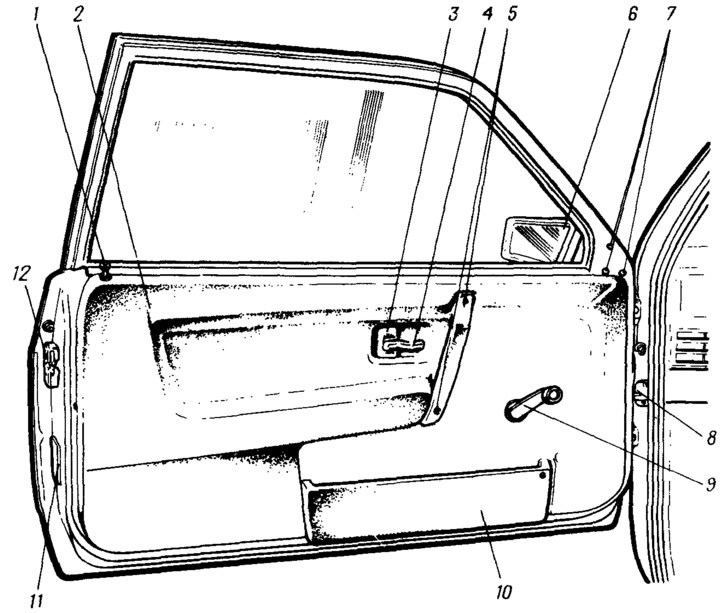
Pic. 138. View of the front door from the inside:
1 - lock off button; 2 - door upholstery; 3 - lining of the inner handle; 4 - inner door handle; 5 - screws for fastening the armrest handle; 5 - external rear-view mirror; 7 rear-view mirror mounting screws; 8 - door opening limiter; 9 - power window handle; 10 - door upholstery pocket; 11 - reflectors; 12 - external door lock.
The doors consist of stamped steel outer and inner panels, profiled frames of the door windows and reinforcements, which are interconnected by bending the flanges of the outer panels and contact welding.
Doors are equipped with cable windows, locks with lock switches, door opening limiters 8. Upholstery of 2 doors is made of non-combustible polyurethane foam covered with PVC film (PVC), and fastened with plastic holders included in the holes of the inner panel of the door. The left door is equipped with a rear-view mirror 6.
Door opening limiter does not allow when opening the stop in the body pillar. The flat rod of the limiter 8 is attached at one end to the rack by means of a pin, the other end has a pin that limits the maximum opening of the door. The rod has vyshtampovki on both sides. Steel rollers are pressed against it on both sides, which are inserted into a cracker made of polyamide. The rollers fix the open position of the door by the punching of the rod.
Power window (pic. 139) doors - cable, fastened on the inner panel of the door with nuts to welded bolts. Cable 3 encircles two rollers 4 mounted on the upper and lower brackets of the window guide tube. In building 11 (pic. 140) the cable is wound on the drum 10, the driven gear of which is engaged with the drive gear 9. On the drive roller 2 there is a spring brake that prevents the glass from spontaneously lowering. The drum with the driven gear is installed in the housing 11 and the cover 4 with its hub in two plastic bushings 8.
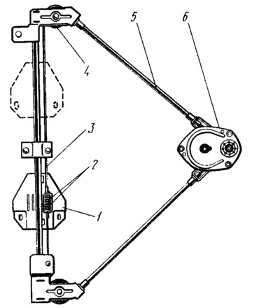
Pic. 139. Power window:
1 - sliding glass mounting plate; 2 - spring for selecting the slack of the cable when it is drawn out; 3 - cable; 4 - roller; 5 - cable sheath; 6 - power window mechanism.
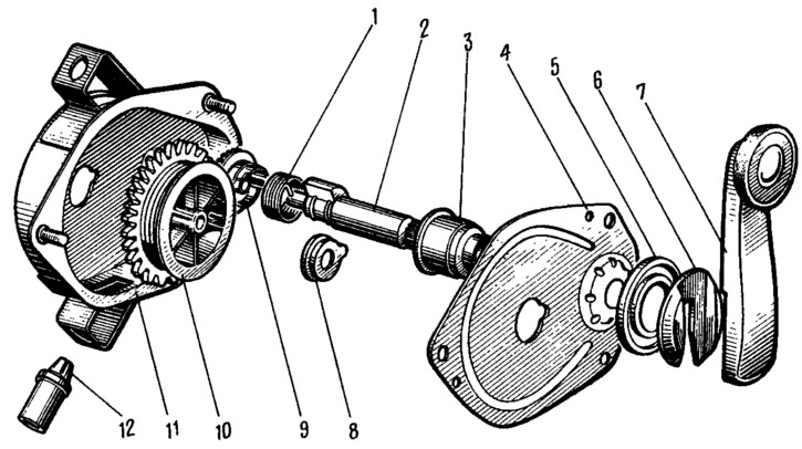
Pic. 140. Power window mechanism:
1 - brake spring; 2 - drive roller; 3 - glass; 4 - cover; 5 - socket; 6 - facing of the handle; 7 - power window handle; 8 - drum support; 9 - drive gear; 10 - drum with driven gear; 11 - body; 12 - tip of the cable sheath.
Plate 1 can move along the guide tube of the power window (see fig. 139) glass lifting. There are springs 2 in the plate bracket, which provide tension to the cable as it is pulled out. The middle part of the cable is attached to the drum.
Lever 7 (see fig. 140) The window lifter is installed on the splines of the drive shaft 2 and is fastened with the help of the facing 6 of the handle, which, when installed on the handle, enters the annular groove of the drive shaft. A plastic socket 3 is placed under the handle, pressed by the door upholstery to the power window handle.
The sliding glass holder is attached with two bolts to the glass lifting plate. Glass guides are attached to the inner panel of the door.
This design of the power window eliminates its adjustment. During operation, only checking the fastening of parts is required.
Door lock (pic. 141) - rotary type, consists of external and internal locks and a latch on the central pillar. Locks are fastened with screws to the end of the door.
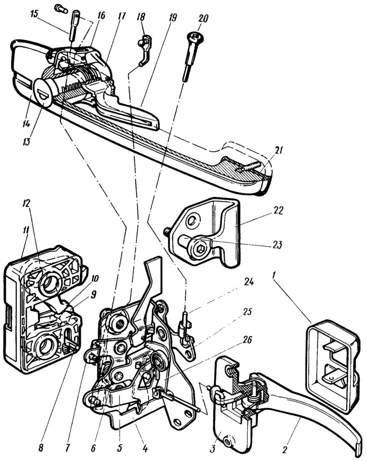
Pic. 141. Front right door lock:
1 - lining of the inner handle; 2 - inner door handle; 3 - an arm of the internal handle; 4 - body of the internal lock; 5 - lever of the external drive of the lock; 6 - intermediate lever; 7, 25 - shutdown levers; 8 - lock drive pin; 9 - doggy; 10 - ratchet; 11 - cover of the external lock; 12 - body of the external lock; 13 - lock switch; 14 - outer handle; 15 - external drive lever rod; 16 - key leash; 17 - lock switch leash; 18 - pull-off; 19 - key; 20 - lock off button; 21 gasket; 22 - latch body; 23 - latch pin; 24 - pull button off; 26 - internal drive lever.
When the door is closed, the ratchet 10 is acted upon by the latch pin 23. The ratchet turns and the pawl 9, under the action of a spring, locks the ratchet by the tooth of one or the other end of the ratchet. Ratchet teeth provide preliminary and full locking of the door. Pre-locking prevents spontaneous opening of the door in case of accidental incomplete closing. Incomplete closing of the door is easy to determine by the knock of the latch pin in the ratchet or by the possibility of some movement of the door when it is pulled up. The ratchet 10 and the pawl 9 are mounted on the axes of the outer lock. The front end of the lock drive pin 8 enters the internal lock.
The outer door handle 14 with a spring-loaded key 19 and a lock switch 13 is attached to the outer door panel through a sealing gasket 21 with two nuts. The leashes 16 and 17 of the key and the lock switch are connected by rods, respectively, with the levers 5 of the external drive and the intermediate lever 7 of the lock.
When you press the key 19 of the outer handle, its leash 16 presses on the rod 15 and acts on the lever 5 of the external drive, which in turn acts on the finger of the intermediate lever 6. The intermediate lever 6 presses on the finger 8 of the lock drive, which retracts the pawl 9 and releases the ratchet 10. Under the pressure of the compressed seal, the door opens.
When pulling the inner handle 2 of the door, the rod of the inner drive turns the lever 26 of the inner drive, which presses the intermediate lever 6 with the second end and releases the ratchet 10 through the pin 8. The door opens.
To prevent access to the car interior from the outside, the lock is turned off, which blocks the operation of the outside handle. When you press the button 20 to turn off the lock, the rod 24 of the button turns the two-arm lever 25, which presses the lever 7 with the second shoulder. The lever 7 takes the intermediate lever 6 to the side, which eliminates the possibility of influencing the pawl 9, and consequently, the release of the lock ratchet.
Turning the lock off and on can be done with the off button or the door lock switch. When the lock key is turned, the switch leash 17 acts directly on the lock release lever 7 through the release rod 18.
When the door is closed, the cover 11 of the outer lock extends beyond the edges of the latch body 22 and does not allow the door to spontaneously open in the event of a collision or overturning of the car, when, due to deformation of the door or body opening, the lock ratchet tends to disengage from the latch pin in the direction of the longitudinal axis of the car.
The position of the latch can be adjusted due to the increased dimensions of the holes on the rack. Before adjustment, it is recommended to outline the contours of the lock retainer on the body pillar. If the door closes too tightly, loosen the fixing screws of the latch, move it outward and tighten the screws. If the door closes weakly, the latch is shifted inward. In this case, there should not be a recession or protrusion of the door relative to the body. If the door drops when closing, the latch should be raised. If the door rises when closed (sag in open position), the latch is lowered. Adjustment also ensures alignment with the lock and the location of the door flush with the surface of the body. In order not to disturb the adjustment of the latch, a gasket made of sanding waterproof skin is installed under it. The spacers under the latch adjust the distance of the latch from the rack so that the latch pin does not touch the outer lock cover.
Mechanisms of locks and a latch according to the design and durability meet safety requirements. For safety reasons, the location of the internal handles on the door and their shape are chosen in such a way as to exclude the possibility of opening the door if the handle is accidentally touched. The axis of the inner handle 2 is located in a plastic bracket 3, which is fastened with two screws to the inner panel of the door and closed with a plastic lining 1, held on the ends of the handle axis protruding from the bracket. The position of the inner handle is adjusted by moving its bracket through the oval holes on the inner door panel for mounting screws. If the door is poorly unlocked by the inner handle, then loosen the bracket fastening screws and move the handle together with the bracket to the desired position. Then tighten the screws.
Due to the oval holes in the hinges for the bolts of the door to the A-pillar, a slight adjustment of the gap between the door and the body is allowed. The gaps between the door and the body at the top and bottom must be the same. When adjusting, loosen the hinge fastening bolts, set the gaps taking into account the draft of the door after loading it and tighten the bolts. The magnitude of the shift of the loops relative to the initial position is easily determined from the previously outlined contours of the loops on the A-pillar. For the draft of the door, it is loaded with a load of 100 kg applied in the lock area. The load is applied to the door, ajar at an angle of 5°, with a uniform increase in the load from 0 to 100 kg and then a uniform decrease to 0. After the door has settled, the gaps are checked again and, if necessary, the adjustment is repeated.