
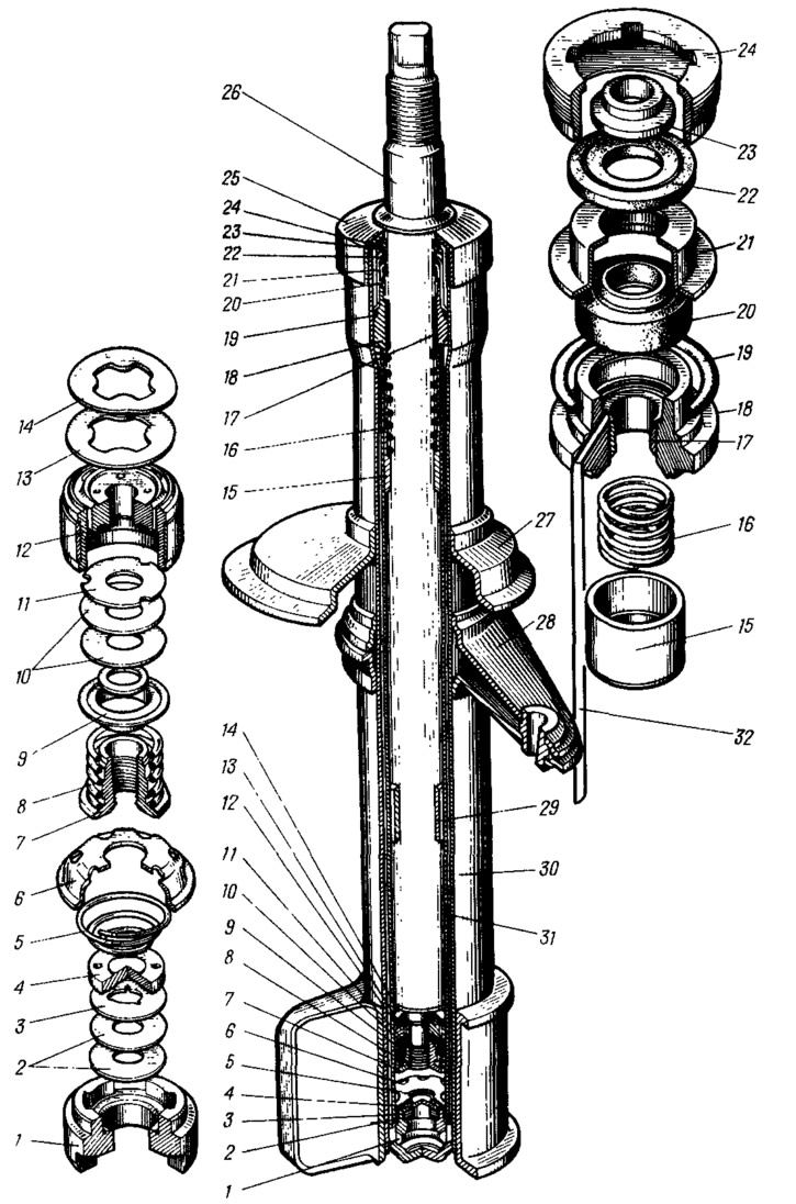
Pic. 70. Telescopic stand:
1 - compression valve body; 2 - flats of the compression valve; 3 - throttle disk of the compression valve; 4 - compression valve plate; 5 - compression valve spring; 6 - clip of the compression valve; 7 - recoil valve nut; 8 - recoil valve spring; 9 - recoil valve plate; 10 - recoil valve disk; 11 - throttle disc of the recoil valve; 12 - piston assembly with ring; 13 - bypass valve plate; 14 - bypass valve spring; 15 plunger; 16 - plunger spring; 17 - guide bushing of the rod with a fluoroplastic layer; 18 - holder of the guide sleeve of the rod; 19 - sealing ring of the rack body; 20 - stem gland; 21 - stuffing box holder; 22 - gasket of the protective ring of the rod; 23 - protective ring of the rod; 24 - rack housing nut; 25 - compression buffer support; 26 - stock; 27 - spring cup; 28 - rotary lever; 29 - stem restrictive sleeve; 30 - rack housing; 31 - cylinder; 32 - drain tube.
A cylinder 31 is installed in the rack body, in the lower part of which a compression valve 1 is pressed in. Its body is pressed against the bottom of the rack body. The compression valve consists of body 1, discs 2 and 3, disc 4, spring 5 and clip 6. The body of the compression valve is metal-ceramic. In its upper part, a socket with a chamfer is machined, covered by disks, which are pressed against the socket through plate 4 by spring 5. The upper end of the spring rests against holder 6, which is put on the cylindrical belt of the compression valve body. To ensure the passage of fluid from the rack housing to the cylinder and vice versa, a cylindrical groove and four vertical channels are made in the lower part of the housing. The same grooves are found in the upper part of the compression valve housing.
Disks 2 of the compression valve are flat, made of steel tape, 0.15 mm thick, have a hole in the center for the passage of fluid. In the central hole of disk 3, three cutouts are made for throttling the liquid at a low speed of the rod. The plate 4 has a cylindrical protrusion in the lower central part, which overlaps the central hole of the disks 2 and 3, but does not close the throttling cutouts. When assembled, a gap is formed between the plate 4 and the disk 3 for the passage of liquid. For the same purpose, eight holes are made along the periphery of the plate. The clip has a flare and a cylindrical seat belt, on which the cylinder is mounted, which provides the necessary tightness between the compression valve and the cylinder 31. On the stamped surface of the clip, there are six side and one central hole for the passage of fluid.
The cylinder contains a rod 26 with a piston 12 assembled with valves. The ceramic-metal piston has twelve vertical channels arranged along circles of two diameters. Four channels located along a larger radius are closed by a plate 13 of the bypass valve, pressed against the channels by a flat spring 14. The remaining channels are blocked from below by a package of two (initial version of three) recoil valve disks. The upper disk 11 is throttle, it has three cutouts along the outer edge. The next 10 discs are flat. The package is pressed against the piston by a spring 8 through the support plate 9. The piston assembly with valves is attached to the stem with a nut 7, which is tightened with a torque of 1.2... 1.6 kgf·m and fixed by punching the stem in two places. A washer is installed between the disks and the nut to protect the recoil valve disks from damage and stabilize the valve operation.
The piston is sealed in the cylinder with a ring made of filled fluoroplastic, due to which the wear resistance of the pair: cylinder-piston increases sharply. A restrictive sleeve 29 is pressed onto the rod and then welded, which, resting against the plunger 15 of the hydraulic recoil buffer, limits the recoil stroke.
The hydraulic recoil buffer consists of a plunger 15 and a spring 16, under the action of which the plunger falls down until it stops against the protrusion of the cylinder. A gap is made between the stem and the plunger, through which the cavities above and below the plunger communicate. Between the top of the plunger and the cylinder there is a calibrated gap for fluid throttling when the gap between the stem and the plunger is closed. There is a significant gap between the rest of the plunger and the cylinder, due to the expansion of the cylinder part.
The rod guide is a split sleeve 17 with a fluoroplastic insert, which is pressed into the guide cage 18. A drain tube 32 is installed in the cage channel, connecting the upper cavity of the cage with the annular groove of the telescopic rack housing. This tube drains the liquid that has passed through the gap between the stem and the sleeve so that there is no foaming of the liquid due to contact with air. The cage assembly with the guide sleeve is pressed onto the cylinder by a cylindrical belt.
From above, a self-clamping gland 20 of the frame type with a clip 21, a gasket 22 and a protective ring 23 of the stem are installed in the body of the telescopic rack. All parts in the rack body are pressed against the bottom of the body with nut 24. Support 25 is pressed onto the rack body, against which buffer 3 rests during compression (see fig. 69) suspension compression stroke limiter.