




A new, tested vehicle in running order and with a payload of 320 kg (4 people and 40 kg of cargo in the trunk) the wheel alignment angles must have the following values:
- Camber — ±30' (from -3 to +3 mm)
- Toe-in: 0±1 mm
- The longitudinal tilt angle of the pivot axis is 1°30'±30'
Before you start measuring the wheel alignment angles, you should check: the air pressure in the tires (must comply with the norm), radial and axial runout of wheels (no more than: axial - 1 mm, radial - 0.7 mm), free play of steering wheel (no more than 5°), technical condition of suspension units and parts (absence of deformations, wear of rubber-metal hinges, unacceptable settlement of upper support of suspension strut and wear of ball joint). Eliminate detected faults.
Place the fully fueled and equipped vehicle on a level surface and load it with a load of 320 kg (4 people + 40 kg of cargo in the trunk). Make sure that the front wheels are set in a position corresponding to the straight-line movement of the vehicle. "Pump" the vehicle suspension by applying a force of 40...50 kgf directed from top to bottom 2-3 times, first on the rear and then on the front bumper.
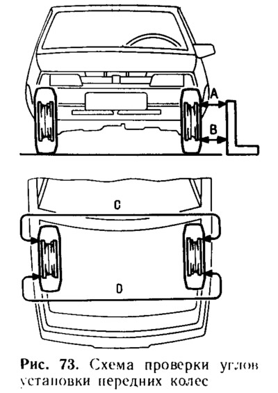
To check the wheel alignment, measure the distance "A" (figure 73) between the wheel rim and the square. Then roll the car so that the wheels turn 180° and measure the distance "B". When the camber angle is correctly adjusted, dimension "A" should be no more than 3 mm larger or smaller than dimension "B". The camber is adjusted with an eccentric bolt 11 (see figure 69) with loose nuts on the steering knuckle mounting bolts. After completing the adjustment, tighten the nuts to a torque of 9 kgf·m.
[The original is posted on Internet resource: VazBook.ru]
After adjusting the camber, check and, if necessary, adjust the wheel alignment. To do this, measure the distance "C" (figure 73) behind the wheels between the points on the rims at the level of their axles. Then roll the car so that the wheels turn 180° and measure the distance "D". If the wheel alignment is set correctly, then the dimension "C" should be equal to the dimension "D". Otherwise, loosen the nuts 4 (figure 76) and, rotating the adjusting rods 5 by the same amount, set the required toe-in. Having completed the adjustment, tighten the nuts 4 to a torque of 12...15 kgf·m, having first made sure that plane "C" of the bottom of the tip 2 is parallel to plane "D" of the support surface of the pivot arm.
The longitudinal tilt angle of the pivot axis is checked and adjusted only on the stand. The longitudinal tilt is changed by changing the number of washers 23 (see figure 69), installed on both shocks of the 29 suspension struts. To increase the longitudinal tilt angle of the pivot axis, reduce the number of washers on the strut in its front or rear part, and to decrease it, add washers, but only in the rear part, since this is not always possible to do from the front due to the short threaded part of the strut. When installing or removing one adjusting washer, the longitudinal tilt angle of the pivot axis changes by approximately 19'. When changing the number of washers on the strut, ensure that the chamfers on the washers are facing the thrust end of the strut. Failure to comply with this rule may result in the struts becoming loose.