
compression stroke. In this stroke, when the wheels of the car go up, i.e. the telescopic rack is compressed, piston 4 (pic. 71) goes down and displaces liquid from the lower part of the cylinder, part of which, overcoming the resistance of the flat spring 2 of the bypass valve 3, flows from the piston space to the over-piston space. All the displaced liquid cannot pass in this way, since the inserted rod 1 occupies part of the volume released by the piston, therefore the other part of the liquid, bending the inner edges of the disks 5 of the compression valve, flows from the cylinder into the rack housing. The compression stroke is limited by the stop of the buffer 3 against the support 4 (see fig. 69).
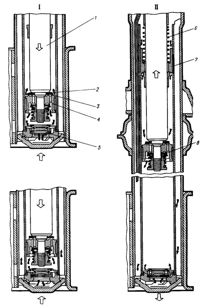
Pic. 71. Scheme of operation of the telescopic rack:
I - compression stroke; II - recoil course;
1 - stock; 2 - bypass valve spring; 3 - bypass valve plate; 4 piston; 5 - compression valve disks; 6 - plunger spring; 7 - plunger; 8 - recoil valve disks.
With a smooth stroke of the stem, the force from the fluid pressure will not be enough to press the inner edges of the compression valve discs, and the fluid will pass into the strut body through three cutouts of the throttle disc 3 (see fig. 70).
Recoil stroke
In this course, the wheels of the car, under the action of the elastic elements of the suspension, go down and the rack is stretched, i.e., the piston goes up. At the same time, above the piston 4 (see fig. 71) fluid pressure is created, and a vacuum is created under the piston. The liquid from the over-piston space, overcoming the resistance of the spring, bends the outer edges of the valve disks 8 and flows into the lower part of the cylinder. In addition, due to rarefaction, part of the liquid from the body, bending the outer edges of the compression valve discs from the valve body, fills the lower part of the cylinder.
At a low piston speed, when the fluid pressure is insufficient to press the recoil valve disks, the liquid through the side cutouts of the throttle disk 11 (see fig. 70) will be throttled, creating resistance to the recoil.
The limitation of the recoil stroke is provided by a hydraulic buffer consisting of a plunger 7 (see fig. 71) and springs 6. During the recoil, when the stem bushing has not yet rested against the plunger, the cavities above and below the plunger freely communicate through the gap between the plunger and the stem and therefore no additional resistance to the stroke of the stem is created (except for the resistance of the recoil valve). But when the stem sleeve abuts against the end of the plunger and thereby covers the specified gap, and the plunger moves upwards together with the stem, the liquid begins to be forced from the above-plunger space into the sub-plunger space through the calibrated gap between the plunger and the cylinder. At the same time, the resistance to the outflow of fluid through this gap is not constant, since when the plunger rises, the length of the calibrated gap increases, which means that the resistance to the stroke of the rod also increases, and the higher the plunger rises, the greater the resistance increases. Due to the slowing down of the recoil, it is not allowed to transfer significant loads to the suspension parts and to the body.