




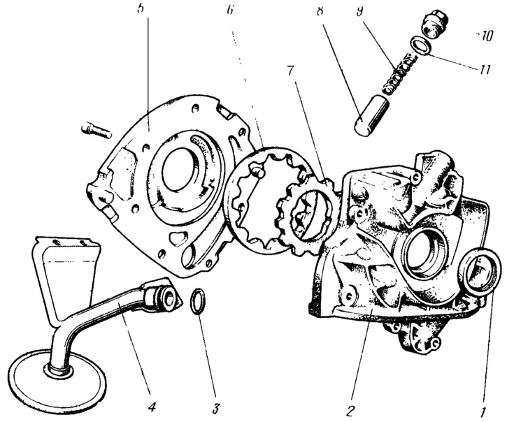
Figure 37. Oil pump parts:
1 - front crankshaft oil seal; 2 - pump cover; 3 - rubber sealing ring; 4 - oil receiver; 5 - pump body; 6 - driven gear; 7 - drive gear; 8 - pressure reducing valve; 9 - pressure reducing valve spring; 10 - plug. 11 - sealing ring.
The pump consists of a cover 2, a housing 5 with suction and discharge cavities, an oil receiver 4 and a pressure-reducing valve 8. The housing contains the leading 7 and driven 6 gears. To ensure the necessary clearances between the gears and the housing when the temperature changes, the housing is cast from cast iron, and the gears are made of metal ceramics with linear expansion coefficients close to each other.
In the housing, the suction cavity is separated from the discharge cavity by a crescent-shaped protrusion. Cover 2 of the pump is made of aluminum alloy. The pump housing is connected to the cover with screws and sealed with a liquid sealant such as Loctite No.329 or activator No.738 (liquid gasket).
The pump drive gear is mounted on two flats of the crankshaft. Oil leaking to the seal 1 is discharged into the engine crankcase along the grooves on the flats of the gear. The pump gears are of trochoidal engagement, which reduces mechanical losses on the drive and increases the efficiency of the pump compared to gears of involute engagement.
The pump capacity at 6000±120 rpm of the drive gear and a back pressure of 5 kgf/cm² must be at least 34 l/min.
Oil receiver 4 is secured with one bolt to the pump cover and two bolts to the cover of the second main bearing. The oil receiver tube in the pump cover is sealed with a rubber ring B. At the bottom, the oil receiver has a cup with a mesh and a spherical damper, which has a hole in the center, which reduces the possibility of air suction when the engine is tilted.
The discharge channel in the pump cover is connected by a channel to the oil filter. The cover contains a piston-type pressure reducing valve 8. The required valve actuation pressure is provided by spring 9. When the valve is actuated, the oil is bypassed into the pump suction cavity.
When the engine is running, the gears of the oil pump suck oil from the crankcase through the oil receiver and the suction cavity. The cavities of the pump gear teeth drive the oil into the discharge cavity and feed it under pressure through the oil filter to lubricate the rubbing parts. After the engine stops, some of the oil remains in the discharge cavity of the pump and allows the pump to quickly start working after the next engine start.