
When the engine is running, crankcase gases through the exhaust hose 9 (pic. 38) are sucked into the body 8 of the oil separator, where, due to the swirl of the gas flow and the grid 6, the oil is separated. Further crankcase gases can be sucked off in two ways. When the throttle valves are closed and the engine is idling at the minimum crankshaft speed, the gases are sucked off through hose 2 through the carburetor fitting into the throttle space of the carburetor, where they are mixed with the combustible mixture and enter the combustion chambers. The carburetor fitting has a calibrated hole, which limits the amount of exhaust gases, as a result of which ventilation does not have a noticeable effect on the vacuum value in the throttle space at idle.
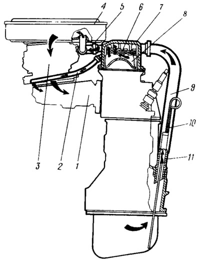
Pic. 38. Scheme of ventilation of the crankcase:
1 - inlet pipeline; 2 - hose for removing carger gases to the throttled space of the carburetor; 3 - carburetor; 4 - air filter; 5 - upper exhaust hose; 6 - oil separator mesh; 7 - cylinder head cover; 8 - oil separator housing. 9 - lower exhaust hose; 10 - oil level indicator; 11 - fitting.
With an increase in the crankshaft speed, when the throttle valves open, the bulk of crankcase gases will be sucked out through hose 5 into the air filter, into the space behind the filter element.
To prevent flames from entering the crankcase when «shot» into the carburetor, mesh 6 also acts as a flame arrester.