
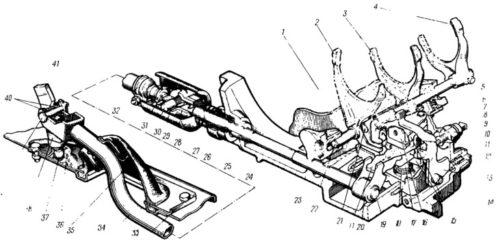
Pic. 62. Gearshift drive:
1 - secondary shaft; shift fork I and II gears; 3 - turn of switching III and IV gears; 4 - fork of inclusion of V transfer; 5 - rod turns on the V gear; 6 - retainer ball; 7 - retainer spring; 8 - latch cover; 9 - guide axis of the locking brackets; 10 - reversing light switch; 11 - three-arm gear selection lever; 12 - plug of the lock of the turn of the reverse gear; 13 - turn on the reverse gear; 14 - gearbox housing; 15 - locking brackets; 16 - housing of the gear selection mechanism; 17 - axis of the gear selection lever; 13 - spring gear selection lever; 19 - gear selection rod; 20 - gear selection rod lever; 21 - a rod of a fork of switching of III and IV transfers; 22 - shift fork rod I and 11 gears; 23 - clutch housing; 24 - bushing; 25 - stem gland; 20 - conical screw fastening the hinge; 27 - sewn cover of the hinge; 28 - housing of the hinge of the gearshift drive; 29 - hinge bushing; 30 - hinge axis; 31 - hinge tip; 32 - a collar of draft of a drive of a gear change; 33 - gear lever housing; 34 - gearshift drive rod; 35 - protective cover of thrust; 36 - ball bearing of the lever; 37 - spherical finger of the lever; 38 - gear lever; 39 - lever finger; 40 - bushing of the lever axis; 41 - locking bracket.
The gear lever with its ball pin 37 rests on a plastic ball bearing 36, which is located in the lever housing 33 fixed to the floor of the body. Two plastic bushings 40 are pressed into the sleeve of the lever 38, through which the finger 39 passes, connecting the lever with the rod 34. The finger is locked by the bracket 41. interconnected by an axle 30. The axle is pressed into the hole of the tip 31, and plastic bushings 29 are installed in the holes of the hinge body.
The gear selection rod 19 is installed in the holes of the clutch housing and its outer end rests on the sleeve 24. At the outlet of the clutch housing, the rod is sealed with an oil seal 25. At the inner end of the rod, the gear selection lever 20 is attached with a conical screw. It interacts with the three-arm lever 11 of the gear selection mechanism. This mechanism is made as a separate unit and is fastened with three bolts to the clutch housing 23. In building 3 (pic. 63) two axles are installed in the gear selection mechanism. A three-arm gear selection lever 4 and two locking brackets 5 are installed on the axis 6, and the axis 7 passes through the brackets 5, fixing them from turning. One arm of gear selection lever 4 serves to engage forward gears, the other to engage reverse gear, and lever 2 of the gear selection rod acts on the third arm.
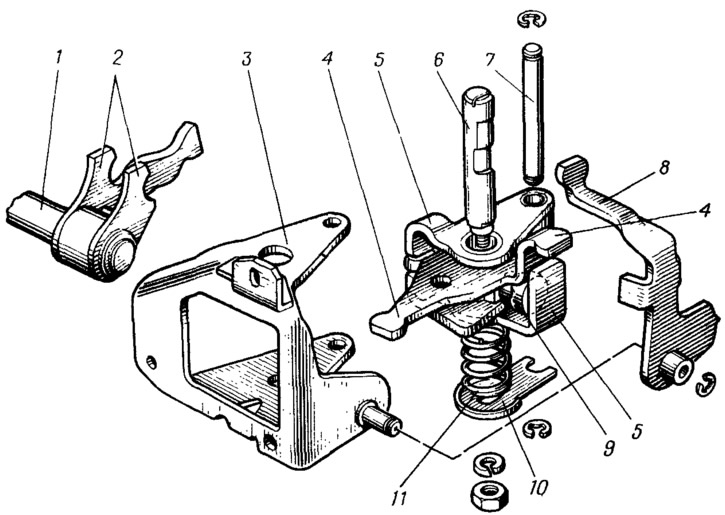
Pic. 63. Details of gear selection mechanism:
1 - gear selection rod; 2 - gear selection rod lever; 3 - housing of the gear selection mechanism; 4 - three-arm gear selection lever; 5 - locking brackets; 6 - axis of the gear selection lever; 7 - guide axis of the locking brackets; 8 - fork of inclusion of a backing; 9 - lock of the gear selection lever; 10 - thrust washer of the gear selection lever; 11 - lever spring.
Under the action of spring 4 (pic. 64,II) the lever 7 and the locking brackets 6 move on their axes until the ball 2 stops against the step on the axis 5. In this position, the brackets lock the reverse fork 1 with one end, entering its groove, and with the other end they lock the first and second gear fork (as well as fifth gear in a five-speed gearbox); the forward gear selector lever is set to the 3rd and 4th gears.
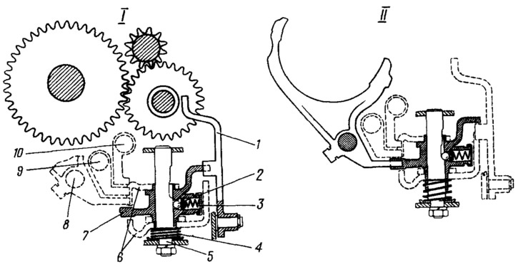
Pic. 64. Gear selection scheme:
I - reverse; II - forward; 1 - fork of inclusion of a backing; 2 - retainer ball; 3 - retainer spring; 4 - spring gear selection lever; 5 - axis of the gear selection lever; 6 - locking brackets; 7 - three-arm gear selection lever; 8 - rod of the shift fork of I and II gears: 9 - rod of the shift fork of III and IV gears; 10 - a rod of a fork of inclusion of V transfer.
When transversely moving the gear lever in the direction of reverse, the force through the rod 34 (see fig. 62) is transmitted to the gear selection rod 19, which, turning on its supports, through the lever 20 moves the gear selection lever II and the locking brackets on their axes. In this case, the spring 4 (see fig. 64,I) is compressed, and the bracket 6 comes out of the groove of the reverse fork 1. Instead of the bracket, the shoulder of the lever 7 of the reverse gear selection enters the groove of the fork 1 and when the lever 7 is turned on its axis, the reverse gear is engaged. Thus, when the gear selection lever is moved along its axis, gears are selected, and when turning on the axis, gears are engaged.
The gearshift drive also includes rods 5 (see fig. 62), 21 and 22 with plugs attached to them. The position of the rods is fixed by ball clamps 6. Fork 4 enters the groove of the synchronizer clutch of the 5th gear, fork 3 enters the groove of the clutch of III and IV gears, the fork 2 enters the groove of the clutch of I, II gears and reverse, and the fork 13 enters the groove of the intermediate gear reverse.