

When the 1st gear is engaged, the synchronizer clutch connects the small crown of gear 6 with the synchronizer hub, which has a rigid connection with the secondary shaft. In this case, the torque is transmitted from the input shaft to the gear 6 and through the clutch 7 to the synchronizer hub and to the output shaft. When the second gear is engaged, the clutch 7 connects the ring gear of the gear 8 with the synchronizer hub, and the torque is transmitted to the output shaft through the gear 8, the clutch 7 and the synchronizer hub.
When the third gear is engaged, the synchronizer clutch 21 connects the gear II to the hub 12, and when the fourth gear is engaged, the same clutch connects the gear 13 to the hub 12, and the torque in both the first and second cases is transmitted through the parts connected by the clutch. When V gear is engaged, clutch 3 (see fig. 62) connects hub 4 with the crown of gear 2, and the torque from gear 7 is transmitted to gear 2 and through the synchronizer parts to the output shaft.
The principle of operation of the synchronizer when the IV gear is turned on is shown in fig. 66.
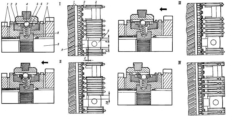
Pic. 66. Scheme of operation of the synchronizer III and IV gears:
I - neutral position; II - the beginning of the inclusion of IV gear; III - completion of the alignment of the angular velocities of gear 1 and shaft 9; IV - full inclusion of IV gear;
1 - driven gear IV gear; 2 - blocking ring; 3 - sliding clutch; 4 - retainer ball; 5 - retainer spring; 6 - retainer cracker; 7 - driven gear III gear; 8 - synchronizer hub; 9 - secondary shaft.
With the neutral position of the sliding sleeve 3 (pic. 66, I) crackers 6 are in the center of the grooves of the hub 8 and do not act on the blocking ring 2. There is a uniform lateral clearance B between the protrusions A of the blocking ring and the grooves of the hub, and between the protrusions A and the crackers there is a gap C.
When turning on IV gear (see fig. 66,II) the sliding clutch 3, moving towards the gear I, carries with it crackers 6, which rest against the ends of the protrusions A of the blocking ring and press it against the conical surface of the synchronizer crown. Under the action of friction forces between the conical surfaces of the blocking ring and the synchronizer crown, as well as the forces of inertia of the synchronized masses, the blocking ring rotates relative to the hub until the ring protrusions stop against the side walls of the hub slots. That is, on the other side of the protrusions, the gap doubles and will be equal to 2V. Due to the circumferential displacement of the blocking ring by 1/4 step, the side bevels of the sliding clutch abut against the bevels of the teeth of the blocking ring and further axial movement of the sliding clutch 3 stops until the angular velocities of gear 1 and shaft 9 are equal (see fig. 66, III). At this moment, the slippage of the friction cones of the blocking ring 2 and gear 1 stops and the force that presses the beveled surfaces of the teeth and the clutch and ring disappears. The released clutch easily moves along the hub, connecting it to the synchronizer crown (see fig. 66, IV).