
Warning! Electrical fault (short circuit) may cause electrical ignition and fire.
If a fuse is blown, replace it; repeated blowing of the same fuse serves as a signal for immediate access to a car service.
Attention! It is strictly forbidden to replace a blown fuse with another one with a larger "denomination", or "bug".
To make troubleshooting easier, obtain a wiring diagram for your vehicle.
If a malfunction of electrical equipment occurs before you have time to buy an electrical circuit, you can fix minor malfunctions yourself, which this section will help you with.
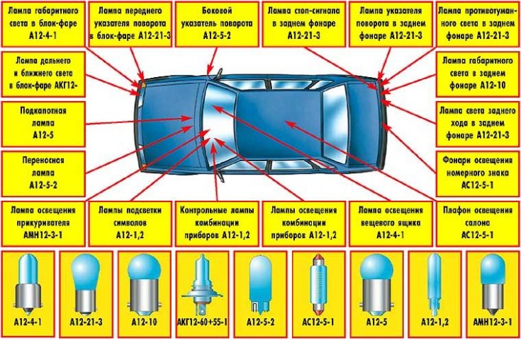
Types and location of lamps
Mounting blocks
On cars of the VAZ-21099 family, two mounting blocks are used - the old 17.3722 and since 1998 the new 2114-3722010-60. The main difference is the use of a new type of fuses: knife-edge instead of cylindrical ones and new compact relays.
Mounting block type 17.3722:

1. Relay for switching on headlight cleaners (K6). 2. Rear window washer time relay (K1). 3. Relay-interrupter for direction indicators and alarms (K2). 4. Windscreen wiper relay (K3). 5. Contact jumpers in place of the lamp health monitoring relay. 6. The relay of inclusion of heating of back glass (K10). 7. Spare fuse. 8. High beam relay (K5). 9. Relay for switching on the dipped headlights (K11). 10. Fuse. 11. Relay for turning on the electric motor of the fan of the engine cooling system (K9). 12. Horn relay (K8).
Mounting block type 2114–3722010–60:
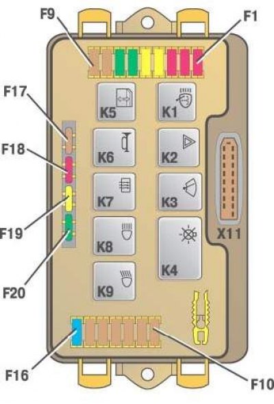
K1. Relay for switching on headlight cleaners. K2. Relay-interrupter for direction indicators and alarms. K3. Windshield wiper relay. K4. Relay for monitoring the health of lamps. K5. Power window relay. K6. The relay of inclusion of sound signals. K7. The relay of inclusion of heating of back glass. K8. Relay for turning on the high beam headlights. K9. The relay of inclusion of a passing beam of headlights. F1-F16. Fuses. F17-F20. Spare fuses.
Circuits protected by fuses
| Fuse number in the mounting block | Protected circuits | |
17.3722 | 2114–3722010–60 | |
1 (8 A) | F9 (7.5 A) | Right fog lamp |
2 (8 A) | F8 (7.5 A) | Left fog lamp |
3 (8 A) | F1 (10 A) | headlight cleaners (at the moment of switching on). Relay for switching on headlight cleaners (contacts). Headlight washer valve |
4 (16 A) | F7 (30 A) | headlight cleaners (in working mode). Relay for switching on headlight cleaners (winding). Heater fan motor. Windshield washer motor. Motorized rear window cleaner. Rear window washer time relay. Valves for switching on the windshield and rear window washers. Relay (winding) turning on the motor of the fan of the engine cooling system. Relay (winding) turning on the heated rear window. A control lamp of heating of back glass. Glove box lamp |
5 (8 A) | F16 (15 A) | Direction indicators and relay-interrupter of direction indicators and alarms (in turn guidance mode). Control lamp of indexes of turn. Rear lights (reversing light bulbs). Motor reducer and relay for switching on the windshield wiper. Generator excitation winding (when starting the engine). A control lamp of falling of level of a brake liquid. Oil pressure drop warning lamp. Carburetor choke control lamp. Parking brake warning lamp. Light board lamp "STOR". Coolant temperature gauge. Fuel gauge with reserve warning lamp. Voltmeter |
6 (8 A) | F3 (10 A) | Rear lights (stop lamps). Interior lighting dome |
6 (8 A) | F6 (30 A) | Power windows for front doors. Power window relay |
7 (8 A) | F10 (7.5 A) | License plate lights. Hood lamp. Instrument lighting lamps. Control lamp for outdoor lighting. Panel of illumination of levers of a heater. Cigarette lighter lamp |
8 (16 A) | F5 (20 A) | The electric motor of the fan of the engine cooling system and the relay for its inclusion (contacts). Sound signal and relay of its inclusion |
9 (8 A) | F10 (7.5 A) | Left headlight (side light). Left rear light (side light) |
10 (8 A) | F11 (7.5 A) | Right headlight (side light). Right rear light (side light) |
11 (8 A) | F2 (10 A) | Turn Signals and Hazard Interrupter Relay (in alarm mode). Warning lamp of the alarm system |
12 (16 A) | F4 (20 A) | Rear window heating element. Relay (contacts) turning on the heated rear window. Portable lamp socket. cigarette lighter |
13 (8 A) | F15 (7.5 A) | Right headlight (high beam) |
14 (8 A) | F14 (7,5) | Left headlight (high beam). Control lamp of inclusion of a high beam of headlights |
15 (8 A) | F13 (7.5 A) | Left headlight (dipped beam) |
16 (8 A) | F12 (7.5 A) | Right headlight (dipped beam) |
Specialized Relays
| Designation | Purpose | Marking | |
Block 17.3722 | Block 2114–3722010–60 | ||
K1 | Rear window washer time relay | 452.3747 | — |
K2 | Turn signal and alarm relay | 493.3747 | 495.3747 |
K3 | Windshield Wiper Relay | 522.3747 | 526.3747 |
K4 | Lamp monitoring relay | — | 4412.3747 |
Wiring diagrams
To carry out repair work in the previous sections, you can use the following explanatory wiring diagrams.
Scheme of a contactless ignition system:
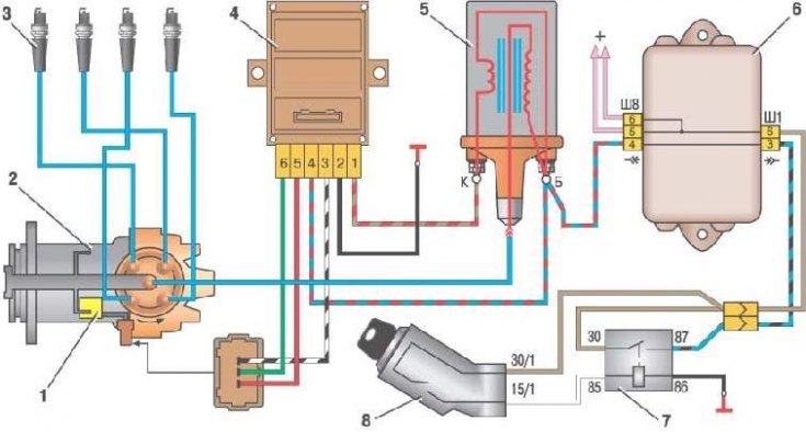
1. Proximity sensor. 2. Sensor-distributor ignition. 3. Spark plugs. 4. Switch. 5. Ignition coil. 6. Mounting block. 7. Ignition relay. 8. Ignition switch.
Carburetor solenoid valve control system:
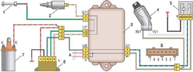
1. Carburetor limit switch. 2. The solenoid valve of the carburetor. 3. Mounting block. 4. Ignition switch. 5. Ignition relay. 6. Control unit. 7. Ignition coil. A. Conclusion "30" generator. B. Numbering of plugs in the control unit.
Generator connection diagram:
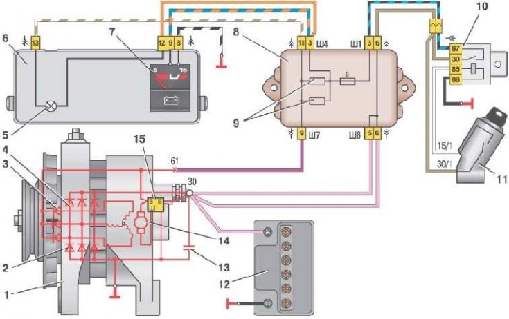
1. Generator. 2. Negative gate. 3. Additional diode. 4. Positive valve. 5. Battery discharge indicator lamp. 6. Instrument cluster. 7. Voltmeter. 8. Mounting block. 9. Additional resistors of 100 Ohm, 2 W. 10. Ignition relay. 11. Ignition switch. 12. Battery. 13. Capacitor. 14. Rotor winding. 15. Voltage regulator.
Scheme of switching on the electric motor of the fan of the engine cooling system on vehicles with mounting block type 17.3722:
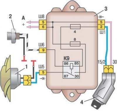
1. Fan motor. 2. The sensor of inclusion of the electric motor. 3. Mounting block. 4. Ignition switch. K9. The relay of inclusion of the electric motor of the fan. A. Conclusion "30" generator.
Starter connection diagram:
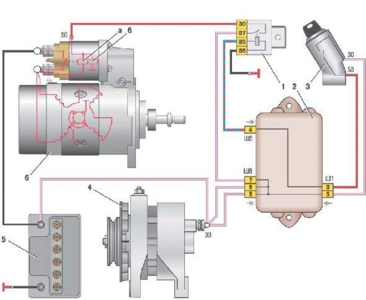
1. Starter enable relay. 2. Mounting block. 3. Ignition switch. 4. Generator. 5. Rechargeable battery. 6. Starter. A. Retractable winding. b. Retaining winding.
Scheme of switching on the electric motor of the fan of the engine cooling system on vehicles with mounting block type 2114-3722010-60:
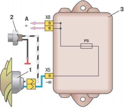
1. Fan motor. 2. Sensor 66.3710 for turning on the electric motor. 3. Mounting block. A. Conclusion "30" generator.