
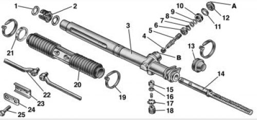
Steering gear details: A, B - labels; 1 – rack bushing ring; 2 – rack support sleeve; 3 - crankcase of the steering mechanism; 4 - roller bearing; 5 - drive gear; 6 - ball bearing; 7 - retaining ring; 8 - protective washer; 9 - sealing ring; 10 - bearing nut; 11 - lock washer; 12 - anther; 13 - protective cap; 14 - rail; 15 - rail stop; 16 - sealing ring; 17 - retaining ring; 18 - stop nut; 19 - collar; 20 - protective cover; 21 - spacer ring; 22 – an internal tip of steering draft; 23 - connecting plate; 24 - locking plate; 25 – a bolt of fastening of draft to a lath
2. Clamp the steering mechanism in a vise with soft sponges.
3. Remove protective cap 13 (see fig.), having previously removed the clamp of its fastening.
4. Remove the clamps 19 for fastening the protective cover 20, the right support and the spacer ring 21, and then the cover 20 from the steering gear housing pipe.
5. With a wrench 67.7812.9537 with an octagonal head, unscrew the nut 18 of the stop and remove the spring and locking ring 17. To remove the stop 15 of the rack, turn the drive gear 5 counterclockwise until it stops. Then, turning the gear another small angle, move the stop. Using special tongs with round jaws inserted into the spring stop recess, remove the rack stop from the crankcase.
6. Remove the boot 12 from the gear and the lock washer 11, unscrew the nut 10 with the key 67.7812.9536. Using a special tool, remove the gear from the crankcase assembly with ball bearing 6.
7. Remove the protective washer 8, retaining ring 7 and press the ball bearing off the gear shaft.
8. Pull out the rack 14 of the steering mechanism towards the removed protective cap 13.
9. Remove the support sleeve 2 rails from the crankcase.
10. If the roller bearing 4 is damaged or worn out, press it out of the steering gear housing with a puller 67.7801.9535.
11. Wash all metal parts in kerosene or cleaning solution. Rinse rubber parts with warm water and wipe with a clean cloth.
12. Carefully inspect the working surfaces of gear 5 and rack 14 for signs of wear, scoring or scratches. Repair minor damage with a fine-grained sandpaper or a velvet file. Replace worn and damaged parts.
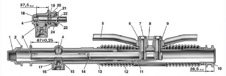
Steering section: 1 - protective cap; 2 - crankcase of the steering mechanism; 3 - rail; 4 - drive gear; 5 – an internal tip of steering draft; 6 - spacer sleeve; 7 – a bolt of fastening of steering draft; 8 - connecting plate; 9 - support sleeve; 10 - support of the steering mechanism; 11 – rack support sleeve; 12 - protective cover; 13 - clamp; 14 - restrictive ring of the rail; 15 - sealing ring of the rail stop; 16 - nut; 17 - rail stop; 18 - roller bearing; 19 - ball bearing; 20 - retaining ring; 21 - sealing ring of the nut; 22 – gear bearing fastening nut; 23 - anther; 24 - lock washer.
13. Ball bearing 6 should rotate freely, without jamming. Bearing 4 must be replaced after pressing out. If in doubt, replace the bearings with new ones.
14. Check the condition of the protective cover 12 (pic. «Steering gear section»), cap 1 and support 10. If they are cracked or torn, replace them with new ones.
15. Check the condition of the support sleeve 2 (see fig. «Steering gear parts») racks and its landing in the steering gear housing. Replace damaged bushing.
16. Replace the sealing rings of the rack stop, drive gear bearing nuts and rubber rings of the rack support sleeve with new ones, regardless of their technical condition. Also replace the clamps and locking plate 24 and washer 11.
Warning! When assembling, pay special attention to ensure that dirt, chips or other foreign bodies do not get into the steering gear housing.
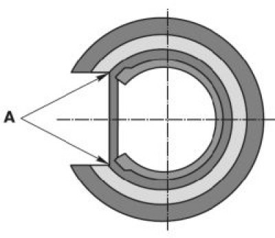
Installing the rack support sleeve: A - the cut of the sealing ring after installing the sleeve in the steering gear housing.
17. Press the ball bearing 6 onto the drive gear shaft with a mandrel 67.7853.9574 until it stops. Using mandrel 41.7853.4006, install retaining ring 7 into the groove on the gear shaft, avoiding its distortion, then install protective washer 8 and sealing ring 9.
18. Install new damping rings 1 into the grooves of the support sleeve 2 so that the thin part of the rings is opposite the cut of the sleeve. Insert the bushing into the crankcase so that its cut part is opposite the hole for the steering rod mounting bolts, and fix it by inserting the protrusions of the bushing into the holes in the crankcase. After installing the support sleeve in the crankcase, cut the rings along the contour of the sleeve, removing the cut off parts (see fig. higher).
19. Press the roller bearing into the steering gear housing with a mandrel 67.7853.9585. Press-in depth 37.5 mm, press-in force 2000–5000 N (203.9–509.7 kgf). In order not to damage the bearing during pressing, the mandrel used must have a stop that limits the depth of pressing.
20. Having generously lubricated the rack teeth with Fiol-1 grease and its other surfaces with a thin layer, install the rack into the crankcase 2 (see fig. «Steering gear section»), sliding it through the support sleeve 11 until it stops in a special device in order to withstand the size (87±0,25) mm from the end of the rail to the axis of the rail stop.
21. Apply Fiol-1 grease to the teeth of the drive gear and put Fiol-1 grease into the ball bearing. Then install the gear in the crankcase so that the flat on its shaft is facing to the right (in the direction of the vehicle), and press the bearing into the crankcase until it stops. Maximum bearing pressing force 1500 N (152.9 kgf).
22. Using the key 67.7812.9536, tighten the drive gear nut to the torque (50±5) N·m [ (5±0,5) kgf·m], install the lock washer 11 as far as it will go (see fig. «;Steering gear parts») and fill the cavity above the nut with Uniol-1 grease.
23. Check and, if necessary, set the drive gear to the position of the rectilinear movement of the vehicle [determined by the size (87±0,25) mm].
24. Put on stop 15 (see fig. «Steering gear parts») rail sealing ring 16 and insert it into the crankcase until it stops against the rail.
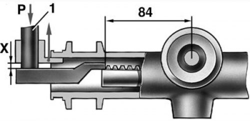
Checking the gap between the rail stop and the nut: 1 - punch
25. Install retaining ring 17, stop spring and tighten nut 18 with wrench 67.7812.9537 to 11–14 Nm (1.12–1.37 kgf·m).
26. Install the fixture on the rail and load the punch 1 (see fig. higher) force P= (500±20) H[ (51±2) kgf], then loosen the nut two notches (24°), to ensure a gap of no more than 0.12 mm between the nut and the rail stop, necessary to compensate for the thermal expansion of parts and manufacturing tolerances for their manufacture. The nut loosening torque must be at least 4.5 Nm (0.45 kgf·m).
27. Install boot 12 on the gear shaft (see fig. «Steering gear parts») so that marks A on the anther and B on the crankcase coincide, and the anther fits snugly against the end of the crankcase. After that, make sure that the torque of the gear in the area of the entire stroke lies within 50–200 N cm (5.1–20.1 kgf cm) at a speed of 30 min-1. If the gear torque is not within the specified limits, determine and eliminate the causes of seizing parts, paying special attention to the rack stop, drive gear and rack. After that, tighten the stop nut 18 at two opposite points, bending the crankcase threads without affecting the nut. For control, mark the position of the nut with paint.
28. Replace protective cover 12 (see fig. «Steering gear section») and a spacer ring so that the right end of the ring is at a distance of 28.5 mm from the end of the pipe; fasten the cover with clamps. Then install support 10 so that it fits snugly against the spacer.
29. After assembly, make sure that there are no swellings and pinches on the protective cover 12 when the gear is rotated at a frequency of 30 min-1, and the moment of rotation of the gear (at the same speed) in the area of the entire stroke is in the range of 50–200 N cm (5.1–20.4 kgf cm). Otherwise, eliminate the causes of the identified defects. Check the torque of the gear with a dynamometer 02.7812.9501 with an adapter sleeve 67.7812.9540.