
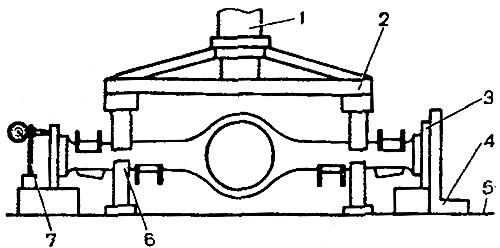
Pic. 3-63. Rear axle beam straightening scheme: 1 - hydraulic cylinder; 2 - clamping traverse; 3 - flange A.70172; 4 - square; 5 - press table; 6 - emphasis; 7 - indicator stand
Install the stand 7 with the indicator so that the indicator leg rests against the upper part of the side surface of the flange, and the indicator pointer is at a division equal to the value of the beam deformation, measured with a probe when checking the beam. On the other side of the beam, install either a stand with an indicator, or a square 4.
Installed under the beam (in the deformation zone) restrictive stops 6, straighten the beam with a hydraulic press sequentially in the horizontal and vertical planes, controlling the results of straightening by the indicator or by the probe on the square 4.
The maximum force of the press during the straightening of the beam must not exceed 98 kN (1000С kgf), to avoid excessive deformation of the section of the casing.
Note. With a stop height of 6, selected correctly by experience, the beam can be corrected without checking with a square or indicator.
Remove the beam from the press and check it as above, replacing flanges A.70172 with «verification».
In the absence of proper equipment, as an exception, it is allowed to edit the rear axle beam sequentially on each side, but with a mandatory check of the deformation of the beam on both sides (see «Checking the rear axle beam»).