
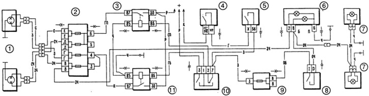
Pic. 7-28. Scheme of switching on headlights and fog light:
1 - headlights; 2 - main fuse block; 3 - relay for switching on the dipped headlights; 4 - ignition switch; 5 - outdoor lighting switch; 6 - control lamps for high beam headlights (left) and fog light (on right); 7 - fog light lamps in the rear lights; 8 - fog light switch; 9 - additional fuse box; 10 - headlight switch; 11 - high beam headlight relay.
Regardless of the position of the switch key 5, you can briefly turn on the main beam of the headlights by pulling the headlight switch lever 10 towards you, i.e., carry out a light signaling. This is ensured by the fact that the voltage on the light signaling contact of the switch 10 is supplied directly from the power sources, bypassing the ignition switch.
On some cars, a headlight hydraulic corrector is installed, which serves to adjust the angle of inclination of the headlight beam from the driver's seat, depending on the load on the car.
The scheme for switching on external lighting is shown in fig. 7-29. The side light in the front and rear lights is switched on by switch 3 for the exterior lighting. At the same time, the lamps of the lanterns 6 of the license plate lighting, the lamps for lighting the instrument cluster and the illumination of switches and displays, as well as the control lamp 5 of the side light, also light up.
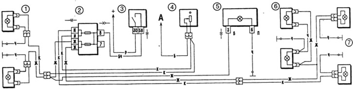
Pic. 7-29. Scheme for switching on outdoor lighting:
1 - side light lamps in the front lights; 2 - fuse box; 3 - outdoor lighting switch; 4 - instrument lighting switch; 5 - control lamp for outdoor lighting in the instrument cluster; 6 - license plate lights; 7 - side light lamps in the rear lights; A - to the lighting lamps of the instrument cluster, switches and backlight display.
The scheme of inclusion of indexes of turn and the alarm system is shown in fig. 7-30. The right and left turn indicators are switched on by switch 10 mounted on the steering column. In the alarm mode, the alarm switch 9 turns on all direction indicators. The flashing of the lamps is provided by the relay-breaker 8.
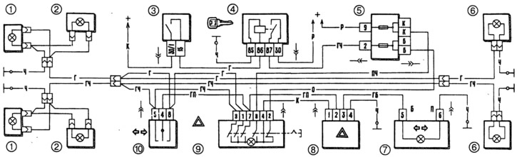
Pic. 7-30. Scheme of switching on direction indicators and alarms:
1 - direction indicator lamps in the front lights; 2 - side direction indicators; 3 - ignition switch; 4 - ignition relay; 5 - fuse box; 6 - turn signal lamps in the rear lights; 7 - control lamp of direction indicators in the instrument cluster; 8 - relay-breaker for direction indicators and alarm; 9 - alarm switch; 10 - turn signal switch.