
Disassembly of the outer hinge
Disassembly of the hinge is carried out only in case of damage to the cover 7 (see fig. 92), when it becomes necessary to flush the hinge parts and replace the lubricant and boot.
For dismantling the outer hinge, tool 67.7814.95081 remove the clamps 5 and 8 and shift the cover 7 along the wheel drive shaft (unscrew cover if necessary).
Using a drift and a hammer, the hinge is knocked off the shaft, applying force to the holder 6. Remove the cover from the shaft, remove the old grease and wash the hinge.
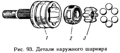
Before disassembling with paint or a touchstone, mark the relative position of the clip 3 (pic. 93), separator 2 and body 1 of the hinge. Fix the outer hinge in a vise, as shown in Fig. 94. Tilt the cage and separator so that one ball comes out of the hinge body as completely as possible (see fig. 94). Excessive force of rotation of the separator is unacceptable, as it is possible to block the balls, which will complicate further disassembly. With a screwdriver made of soft material, squeeze the ball out of the separator. Then all the parts are turned so that the adjacent ball takes the same position, and it is removed from the separator. Using these techniques, take out the remaining balls.
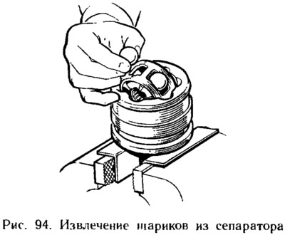
The sequence of removing the balls can be different - through the ball. Slight tapping on the separator or cage with an object made of soft material is allowed.
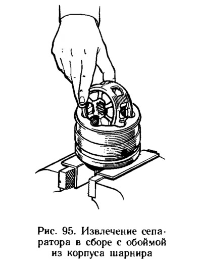
Install the separator with the cage so that the windows of the separator are located against the protrusions of the hinges, and remove the separator assembly with the cage (pic. 95).
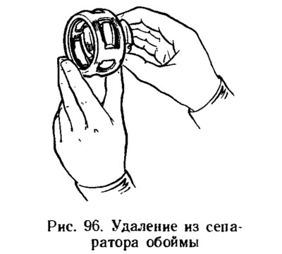
The cage is removed from the separator, for which one of the projections of the cage is placed in the separator window (pic. 96), and roll out the clip. Once again, the hinge parts are thoroughly washed and the condition of all parts is checked, paying attention not only to their wear and damage, but also to the presence of corrosion. If the working surfaces are worn more than 0.1 mm, damaged or corroded, the hinge assembly is replaced.
Assembling the outer hinge
Assembly is carried out in the reverse order of disassembly, taking into account the following:
- before assembly, grease SHRUS-4 is applied to all parts;
- when installing the separator assembly with the cage into the hinge body, it is necessary to ensure that the marks made before disassembly coincide;
- when installing the balls in the separator, the cage is tilted approximately at an angle twice as large as that of the separator;
- fill the hinge with SHRUS-4 grease in the amount of 30 cm3;
- install a new retaining ring in the groove of the shaft strictly in its center, using grease. Then the shaft rests against the cage so that the alignment of the ring relative to the cage is preserved. Sharply hit the end of the wheel drive shaft. In this case, the retaining ring is compressed and slips through the hole of the clip;
- before installing the clamps release «excess» air from the boot by pulling the seat band of the boot away from the drive shaft with a screwdriver.
Check the tightness of the clamps, as well as their condition, including checking for cracks in the area of the fixing and tightening nests of the clamps, their deformation and traces of rubbing on the clamps on the road surface. In case of loose fit and detection of these defects, replace the clamps with new ones.
Disassembly of the inner joint
Disassembly sequence:
- remove clamps 5 and 8 (see fig. 92) and shift the protective cover along the shaft (screw it out if necessary);
- mark the relative position of the parts to be separated, remove the latch 10 from the hinge body, then the shaft 9 assembled with the holder 6, separator 2, balls 4;
- with a screwdriver made of soft material, remove the balls and remove the clip from the separator;
- using the above methods, separate the hinge parts, wash them and carefully check the condition of all parts. In case of wear of working surfaces with a depth of more than 0.1 mm, damage or corrosion of parts, the hinge assembly is replaced.
Inner Hinge Assembly
Assembly is carried out in the reverse order of disassembly. In this case, before installing the cage on the shaft splines, it is necessary to orient it in such a way that the end of the cage closest to the groove faces the end of the shaft. After assembly, make sure that the cage assembly with the separator and balls moves freely along the entire length of the housing grooves from the force of the hand. Otherwise, find out the cause of jamming and, if parts are damaged, replace the hinge assembly. Then, after making sure of the correct assembly, they put 60 cm into the hinge3 SHRUS-4 lubricants. Before installing the clamps, they release «excess» air from the boot by pulling the seat band of the boot away from the drive shaft with a screwdriver.
Notes
1. Two slats with spikes at the ends, 100 mm long and 15 mm wide, pivotally connected to each other through racks welded to the slats. An M10 bolt is screwed into the horse of the upper bar, resting its ends on the lower bar.