
- before attaching the thrust hinge and the lever to the gear selection rod, degrease the threaded holes in the hinge body and on the rod, as well as the hinge fastening screws; apply special glue TB-1324 to the threads of the screws and the gear selector and tighten them;
- a thin layer of sealant TB-1215 is applied to the crankcase seats under the axle shaft seals and the gear selection rod gland housing;
- before installing the oil seals, the clutch release fork and the release bearing, apply a thin layer of SHRUS-4 grease to the ball bearing of the fork and the guide clutch of the clutch release bearing, and Litol-24 grease to the working surface of the oil seals;
- fasteners are tightened to the torques specified in appendix. 1;
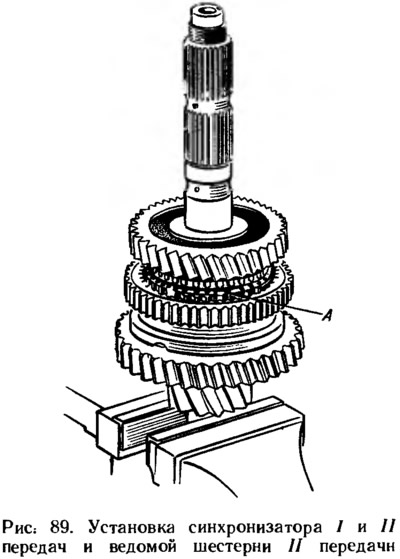
- the secondary shaft is assembled in the reverse order of disassembly, while the synchronizers are installed on the shaft in the assembled state with a mandrel 67.7853.96051;
- when assembling the synchronizer, the blocking rings are installed so that protrusions A are located opposite the sockets of the hub under the springs of the clamps (pic. 89) lesser height, not greater, otherwise, after assembly, gears will not be switched;
- to facilitate the installation of the latch, a little grease is applied to its ball, put it into the cracker and, pressing the spring with a screwdriver towards its socket, put the cracker assembly with the ball in place. At the same time, a nest in the sliding sleeve of the greatest depth should be located opposite the ball;
- needle bearing bushings are pressed onto the shaft with mandrel 67.7853.9605.
The assembly of the differential is carried out in the reverse order of disassembly, having previously lubricated the side gears, washers and satellites with engine oil. The axial clearance of the axle gear must not exceed 0.1 mm, and the moment of resistance to rotation of the differential gears must not exceed 14.7 Nm. With an increased clearance, which is a sign of wear on the parts of the differential, replace the support washers of the gears of the axle shafts with others of greater thickness. If the specified clearance cannot be obtained even when the washers of the greatest thickness are installed, the gears are replaced with new ones due to their excessive wear.
Mandrel 67.7853.95992 press on the differential box the inner rings of the bearings, having previously installed the speedometer drive gear.
Having installed the clutch housing on the stand for assembling the gearbox, mandrel 67.7863.95633 the stem seal is pressed into the socket, and then the gear selector rod is inserted into the crankcase hole and the gear selector lever is fixed on it, having previously degreased the threaded hole in the rod and applied special glue TB-1324 to the lever thread.
Mandrels 67.7853.95932 and 67.7853.96022 the outer rings of the roller bearings of the secondary and primary shafts assembled with separators are pressed into the sockets of the clutch housing, and the inner rings of these bearings are pressed onto the shafts using mandrels 67.7853.95943 and 67.7853.96012. The outer rings of the differential bearings are pressed in with a mandrel 67.7853.95962.
Before pressing in the outer ring of the front bearing of the secondary shaft, a new oil collector 6 is installed in the socket of the clutch housing (see fig. 77).
Install the gear selection mechanism, making sure that the gear selector lever head is inserted into the gear selector lever socket. Fix the gear selection mechanism.
Mandrel 67.7853.96004 press in the input shaft seal. Press ball bearings onto the primary and secondary shafts using the mandrel 41.7853.40065, and screw nuts.
Installed in the crankcase of the differential assembly.
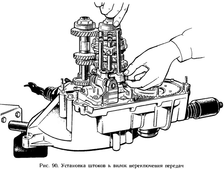
The primary and secondary shafts are installed simultaneously with the gears. Then install the axle with the reverse gear, while making sure that the reverse fork enters the groove of the intermediate gear. Then install the gearshift rods and crackers of the locking device and fix the forks on the rods (pic. 90). The rods are installed alternately with crackers, each subsequent one at the neutral position of the previously installed rods.
A cleaned magnet is installed in the crankcase socket, then a gasket between the clutch and gearbox housings.
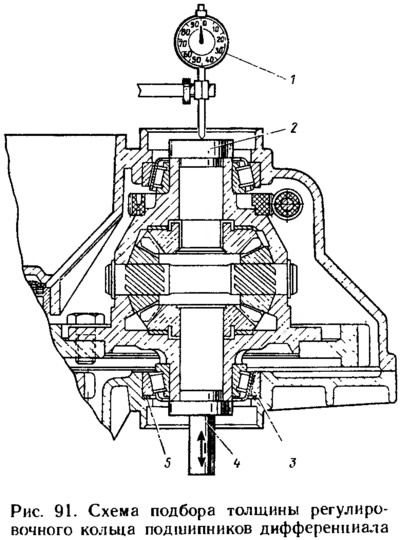
Select the differential bearing adjusting ring as shown below (see sect. «Selection of an adjusting ring for differential bearings»), using tool 67.7824.9517 (see fig. 91).
The bearing nuts of the primary and secondary shafts are finally tightened, having previously locked the input shaft with lock 41.7816. 4070. The selected adjusting ring is installed in the housing of the gearbox housing and the outer ring of the differential tapered roller bearing is pressed in with a mandrel 67.7853.9596. Install the speedometer drive. Install the gearbox housing on the clutch housing and fix it with nuts. Mounting rings are installed in the grooves of the bearings of the primary and secondary shafts. Install the rod retainers in place and wrap the retainer plugs.
Notes
1. Cylindrical tubular mandrel with an outer diameter of 32 mm and an inner diameter of 26 mm.
2. Mandrels 67.7853.9599, 67.7853.9593, 67.7853.9596, 67.7853.9602, 67.7853.9601, 67.7853.9600 are of the same type: cylindrical, with a support, respectively, with diameters of 41, 50, 62, 50, 35, 43 mm and guide shank diameter 23, 20, 55, 25, 12, 20 mm and lengths 22, 14, 5, 16, 22, 15 mm.
3. Mandrels 67.7853.9563 and (67.7853.9594) tubular with outer diameter 29 (20) mm and internal 16.1 (18) mm.
4. Cylindrical mandrel shank with a diameter of 20 mm and a height of 12 mm, a support belt with a diameter of 48 mm, a height of 3-5 mm.
5. Mandrel shank 36 mm in diameter, 13 mm high, support collar 75 mm in diameter, 6 mm high.