
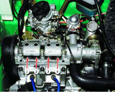
Valve arrangement (counting from the camshaft drive belt):
1 and 4 - exhaust valves
2 and 3 - inlet valves
You will need:
- key "on 10", balloon wrench
- screwdriver
- probe set
- valve clearance adjuster
- tweezers or pliers with narrow jaws
- micrometer (if necessary)
Remove the air filter (see subsection 10.10.1.).
To compensate for the thermal expansion of the valve, a gap between the end of the valve stem and the camshaft cam is structurally specified. With an increased clearance, the valve will not open fully, and with a reduced clearance, it will close completely. The gap is measured with a feeler gauge on a cold engine (at 20°С) between the camshaft cam (the cam must be pointing up from the pusher) and adjusting washer of the valve lifter. The nominal clearance for the intake valve is (0,2±0,05) mm, and for graduation - (0,35±0,05) mm. The gaps are adjusted by selecting the thickness of the shims. Spare parts are supplied with washers with a thickness of 3 to 4.5 mm (through 0.05 mm).
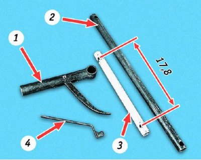
Valve clearance adjuster: 1 - a device for compressing valve springs; 2 - tube for VAZ (4-cylinder engine); 3 - tube for "Oki" (2-cylinder engine); 4 - latch
In the absence of a special device for "Oki" you can use the device for front-wheel drive VAZ models. In this case, instead of the tube supplied with the device, select a tube of the same diameter and at least 21 mm long. Drill two holes in it with a diameter of about 10 mm at a distance of 17.8 mm or drill an additional hole in the tube 2 supplied with the fixture, according to the indicated dimensions (in this case, the device can only be used to adjust the gaps "Oki").
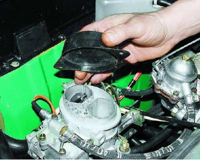
1. Close the carburetor with a plug or a clean rag.
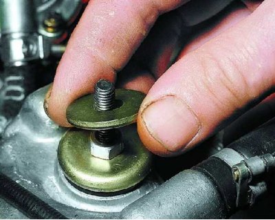
2. Remove the washers from both studs securing the head cover.
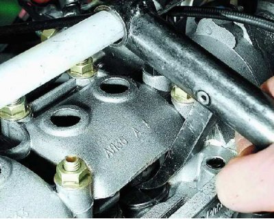
3. Loosen the two nuts securing the head cover.
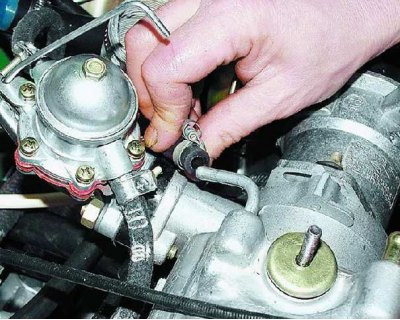
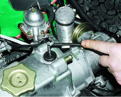
4. After loosening the clamps, remove the hose of the small branch of the crankcase ventilation from the fitting of the head cover...
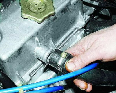
5.... a ventilation hose from the nozzle of the head cover and...
6.... the hose of the large ventilation branch from the fitting of the head cover.
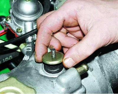
7. Remove the washers from both studs securing the head cover.
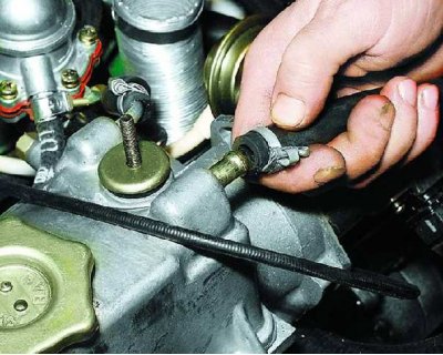
8. Set aside the carburetor choke linkage.
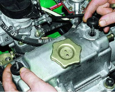
9. Remove the rubber bushings from both studs securing the head cover (Replace loose, deformed and torn bushings).
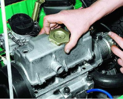
10. Remove the cylinder head cover.
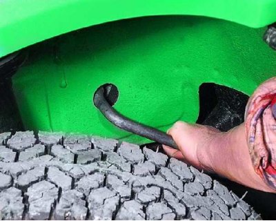
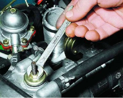
11. Turn the crankshaft with a balloon wrench on the bolt securing the alternator drive pulley through the hole in the right wheel well (to make it easier to turn the shaft, you can unscrew the spark plugs) so that...
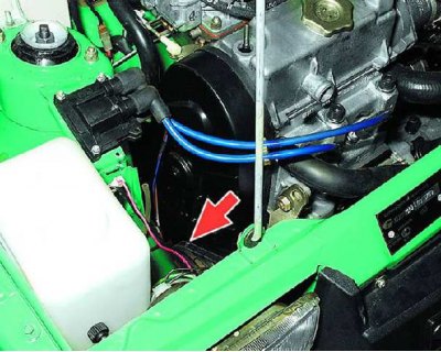
12.... the marks on the alternator drive pulley and on the front cover of the camshaft drive coincided. In this case, it is possible to adjust the clearances in the drive of either the 1st and 2nd, or the 3rd and 4th valves. The order in which the valves are adjusted does not matter. Note that...
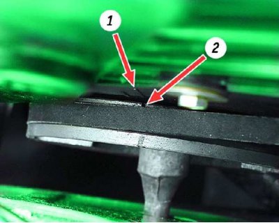
13....there are two marks on the lid. In this case, it is necessary to focus on the long mark 1. Mark 2 is applied on the inside of the pulley. For convenience, duplicate it, for example with a felt-tip pen, on its outer part.
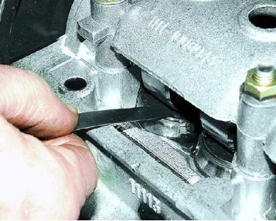
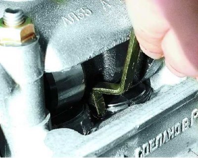
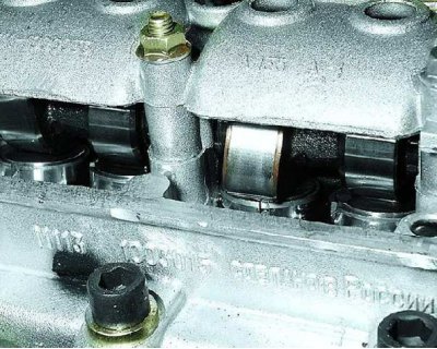
14. Measure the clearances in the valve drive of one of the cylinders with a flat feeler gauge. Replace adjusting washers of those valves in which backlashes differ from nominal. Write down the measured clearances.
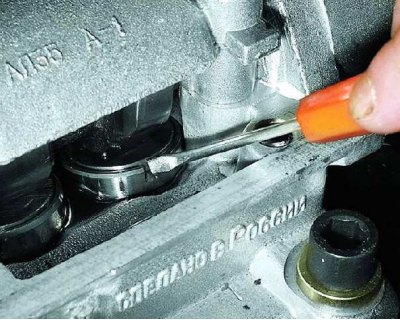
15. To make it easier to remove the adjusting washer, two grooves are made in the pusher. Use a screwdriver to turn the pusher by the groove so that it is convenient to pry the washer. For ease of operation, remove oil from the top of the block head around the valve lifters.
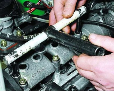
16. Install the special tool on the head cover mounting studs.
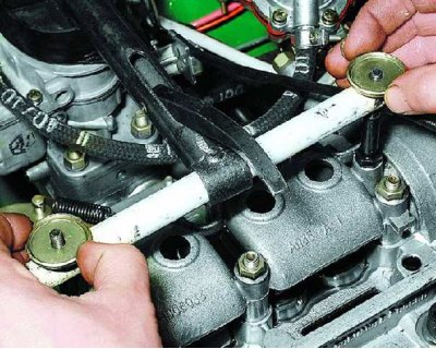
17. Put the washers on the studs, turning them over so as not to crush the flanging on them.
18. Secure the fixture with the nuts securing the head cover.
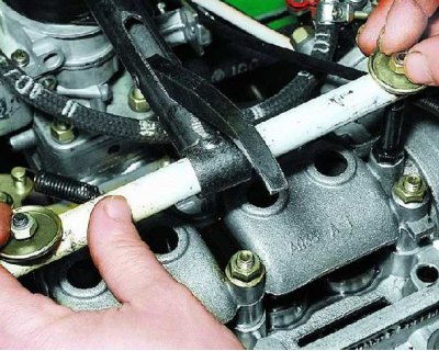
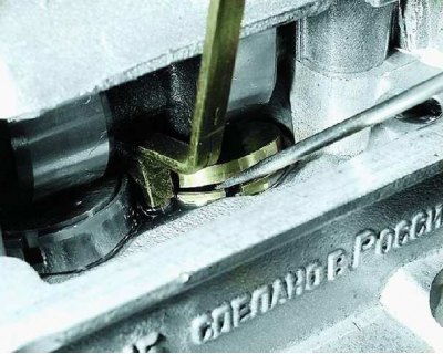
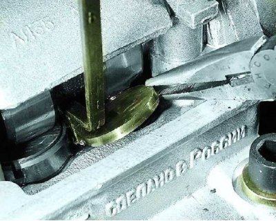
19. By pressing down the lever of the adaptation, drown the pusher, on which the adjusting washer is replaced. Then...
20....insert the retainer under the camshaft so that...
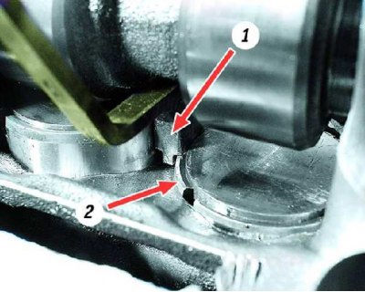
21.... the protrusion on the latch 1 fixed the pusher 2 in the recessed position.
22. Pry the adjusting washer with a screwdriver and...

23.... using, for example, tweezers, remove the washer from the pusher.
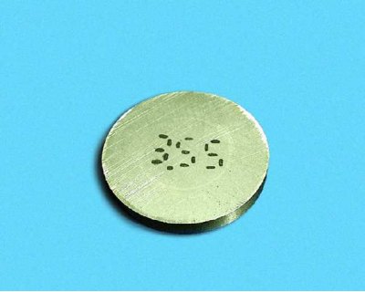
24. Write down the thickness of the shim, the value of which is marked on one of its sides.
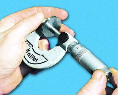
25. If the inscription is not visible, measure the thickness of the washer with a micrometer.
26. Calculate the thickness of the new shim using the formula: (all values in mm)
H = B + A – C,
where H is the thickness of the new washer
B - thickness of the old washer
A - the value of the measured gap
C - nominal clearance
For example (for intake valve): A = 0.26 mm, B = 3.75 mm, C = 0.2 mm, then H = 3.75 + 0.26 - 0.2 = 3.81 mm. Within clearance tolerance (±0.05 mm) we select the closest washer in thickness - 3.8 mm.
27. Install a new washer in the pusher with the thickness calculated according to the formula with the inscription down (to the pusher). Drown the pusher with a tool and remove the retainer. Recheck the clearance and re-adjust if necessary.
28. Rotate the crankshaft one revolution (360°) and adjust the valve clearances of the other cylinder in the same order. Then pour oil into the top of the block head if it has been removed.
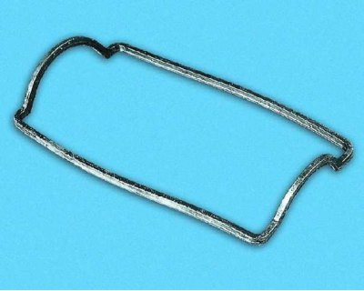
29. Check the condition of the head cover gasket, replace if necessary. Install all removed parts in the reverse order of disassembly.