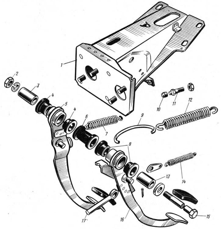
Pedals 16 (pic. 138) clutch and 5 brakes are suspended on the bracket 1 by means of an axle made in the form of a bolt. The axis is fixed with a nut 2 in the holes of the cheeks of the bracket. On the axis between the cheeks of the bracket and the distance sleeve 6, the inner sleeves 3 and 13 of the clutch and brake pedals are clamped. Pedals are pivotally mounted on these bushings, in the hubs of which outer bushings are pressed in and pushers 17 are pivotally attached to both pedals, acting on the pistons of the hydraulic cylinders. The reverse travel of the clutch pedal is limited by a buffer mounted on the head of the screw 11. The main cylinders of the clutch release drive and the brake drive are attached to the vertical shelf of the bracket 1 (see also fig. 61).
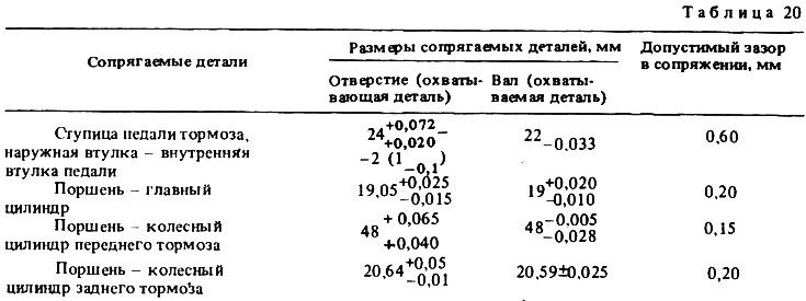
The dimensions of the main mating parts and the limits of permissible wear are given in Table. 20.