




Unscrew the bolts that secure the regulator to the bracket and the bracket to the body, remove the regulator mounting bracket, and then, lowering the regulator down, disconnect the drive lever from it. Plug the pressure regulator holes and pipelines.
The pressure regulator is installed in the reverse order with the rear axle of the vehicle suspended. Before tightening the pressure regulator mounting bolts, install the 67.7820.9518 device on the end of the drive lever (2, Fig. 141). The rod of the device is directed upwards until it stops against the body. This sets the distance (140±5) mm between the end of the lever 1 and the body side member.
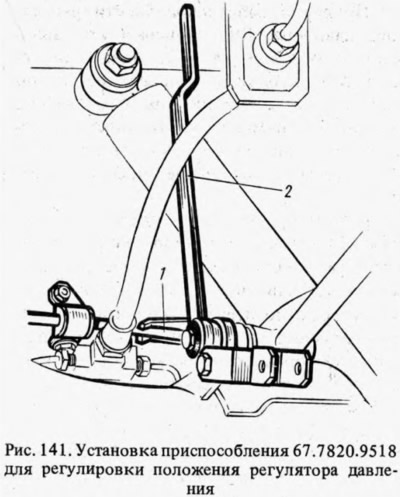
Lift the protective cap 1 (see fig. 139) and, by turning the pressure regulator on the mounting bolts, they achieve that the end of the lever is in light contact with the regulator piston.
Holding the regulator in this position, tighten its mounting bolts until they fail, then coat axle 2 and the protruding part of the piston with a layer of DT-1 grease. Install protective cap 1 in place, placing 5-6 g of the same grease in it.
The original is posted on Internet resource: www.VAZbook.ru
Remove device 67.7820.9518 and connect the end of the lever to rod 7, having previously lubricated bushings 6 of the hinge joint of the rod with the lever with DG-1. Attach the exhaust system pipes to the body. Bleed the brakes to remove air from the rear brake drive.