Open large image in new tab »
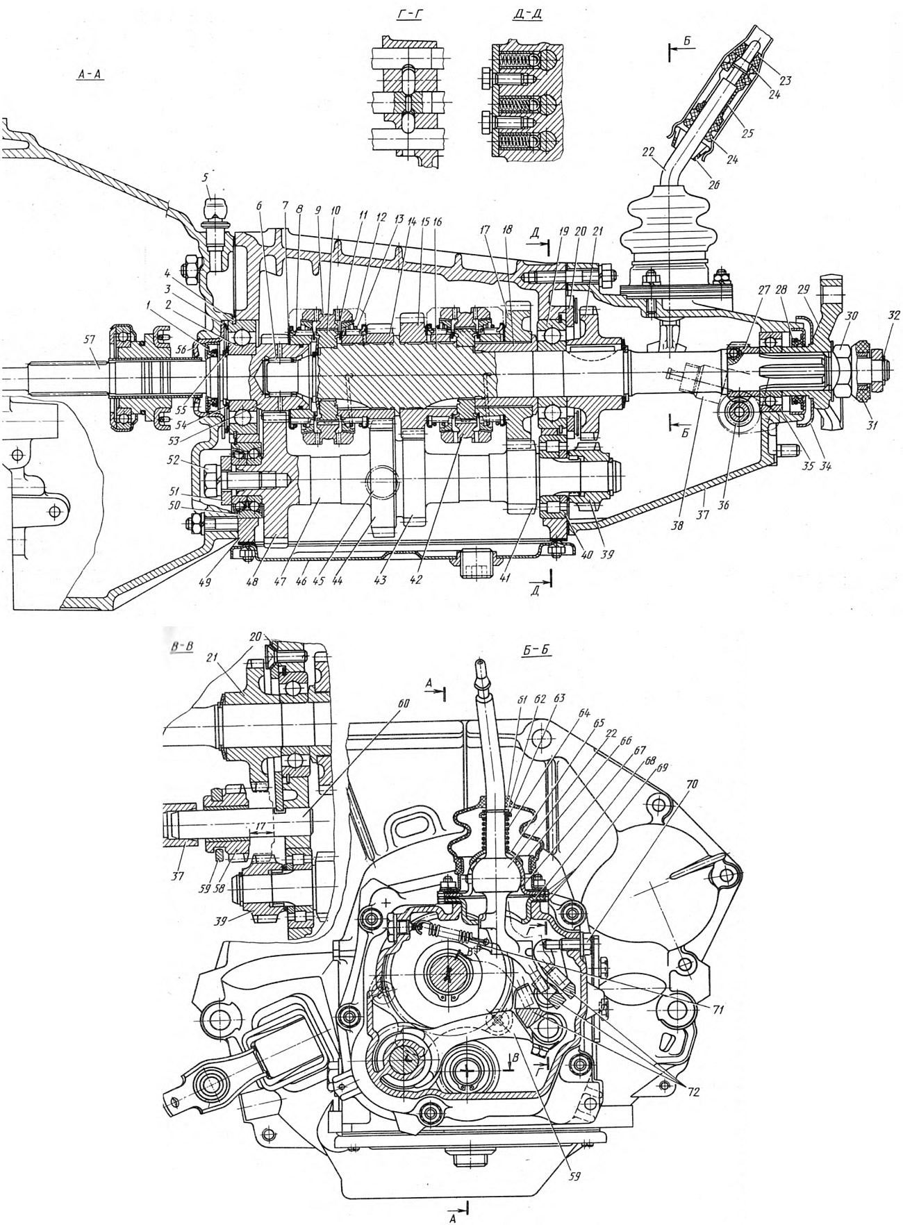
Fig. 66. Gearbox:
1 - drive shaft seal; 2 - rear bearing of the drive shaft; 3 - clutch housing; 4 - bearing mounting ring; 5 - breather; 6 - driven shaft needle bearing; 7 - Thrust washer of the IV gear synchronizer spring; 8 - toothed ring of the 4th gear synchronizer; 9 - synchronizer clutch of III and IV gears; 10 - synchronizer clutch hub; 11 - synchronizer locking ring retaining ring; 12 - synchronizer locking ring; 13 - synchronizer spring; 14 - driven gear of the 3rd gear; 15 - driven gear of the 2nd gear; 16 - driven shaft; 17 - driven gear of 1st gear; 18 - 1st gear bushing; 19 - intermediate bearing of the driven shaft; 20 - locking plate; 21 - reverse driven gear; 22 - lever rod; 23 - thrust cushion; 24 - elastic pillow; 25 - spacer sleeve; 26 - locking sleeve; 27 - speedometer drive pinion; 28 - driven shaft seal; 29 - elastic coupling flange; 30 - nut; 31 - centering ring seal; 32 - retaining ring; 33 - centering ring; 34 - mud deflector; 35 - rear bearing of the driven shaft; 36 - driven gear of the speedometer drive; 37 - rear cover of the gearbox; 38 - speedometer drive; 39 - Reverse drive pinion; 40 - intermediate shaft rear bearing; 41 - 1st gear drive pinion; 42 - synchronizer clutch of 1st and 2nd gears; 43 - 2nd gear drive pinion; 44 - leading gear of the 3rd gear; 45 - filler and inspection hole plug; 46 - gearbox lower cover; 47 - intermediate shaft; 48 - intermediate shaft constant mesh gear; 49 - gearbox housing; 50 - front bearing of intermediate shaft; 51 - bearing clamp washer; 52 - bolt; 53 - constant mesh gear of the drive shaft; 54 - spring washer; 55 - retaining ring; 56 - Front gearbox cover; 57 - drive shaft; 58 - reverse intermediate gear; 59 - Reverse gear fork; 60 - reverse intermediate gear axle; 61 - inner cover; 62 - retaining ring; 63 - washer; 64 - spring; 65 - spherical washer; 66 - flange; 67 - ball joint; 68 - guide cup; 69 - gaskets; 70 - limit bolt; 71 - return spring; 72 - gear shift fork sliders (rods).
1 - drive shaft seal; 2 - rear bearing of the drive shaft; 3 - clutch housing; 4 - bearing mounting ring; 5 - breather; 6 - driven shaft needle bearing; 7 - Thrust washer of the IV gear synchronizer spring; 8 - toothed ring of the 4th gear synchronizer; 9 - synchronizer clutch of III and IV gears; 10 - synchronizer clutch hub; 11 - synchronizer locking ring retaining ring; 12 - synchronizer locking ring; 13 - synchronizer spring; 14 - driven gear of the 3rd gear; 15 - driven gear of the 2nd gear; 16 - driven shaft; 17 - driven gear of 1st gear; 18 - 1st gear bushing; 19 - intermediate bearing of the driven shaft; 20 - locking plate; 21 - reverse driven gear; 22 - lever rod; 23 - thrust cushion; 24 - elastic pillow; 25 - spacer sleeve; 26 - locking sleeve; 27 - speedometer drive pinion; 28 - driven shaft seal; 29 - elastic coupling flange; 30 - nut; 31 - centering ring seal; 32 - retaining ring; 33 - centering ring; 34 - mud deflector; 35 - rear bearing of the driven shaft; 36 - driven gear of the speedometer drive; 37 - rear cover of the gearbox; 38 - speedometer drive; 39 - Reverse drive pinion; 40 - intermediate shaft rear bearing; 41 - 1st gear drive pinion; 42 - synchronizer clutch of 1st and 2nd gears; 43 - 2nd gear drive pinion; 44 - leading gear of the 3rd gear; 45 - filler and inspection hole plug; 46 - gearbox lower cover; 47 - intermediate shaft; 48 - intermediate shaft constant mesh gear; 49 - gearbox housing; 50 - front bearing of intermediate shaft; 51 - bearing clamp washer; 52 - bolt; 53 - constant mesh gear of the drive shaft; 54 - spring washer; 55 - retaining ring; 56 - Front gearbox cover; 57 - drive shaft; 58 - reverse intermediate gear; 59 - Reverse gear fork; 60 - reverse intermediate gear axle; 61 - inner cover; 62 - retaining ring; 63 - washer; 64 - spring; 65 - spherical washer; 66 - flange; 67 - ball joint; 68 - guide cup; 69 - gaskets; 70 - limit bolt; 71 - return spring; 72 - gear shift fork sliders (rods).
The drive shaft 57 of the gearbox has two toothed rims. The pinion (rim) 53 with helical teeth is in constant engagement with the pinion 48 of the intermediate shaft, and the rim 8 with straight teeth is the rim of the synchronizer of the IV gear. The intermediate shaft 47 is a block of gears mounted on two bearings 50 and 40. The driven shaft 16 is mounted on three bearings, and the front bearing 6 is located in the seat of the drive shaft. Gears 14 and 15 rotate on heat-treated journals of the driven shaft, and the gears on the steel sleeve 18.
The synchronizer consists of a sliding clutch 9 (42), a hub 10, a synchronizer locking ring, rigidly connected to the driven shaft, has external splines on which the sliding clutch 9 is located. The locking ring is connected with its internal crown to the synchronizer crown of gear 14 of the third gear and is constantly pressed by a spring towards the sliding clutch.
The intermediate gear 58 of the reverse gear is freely located on the axis 60. When the reverse gear is engaged, the gear 58 engages with the gears 39 and 21.
Gear shifting is performed by means of a mechanical drive consisting of three slide rods 72, on which forks are fixed, which enter the grooves of the sliding clutches 9 and 42 of the synchronizers, and a fork 59, which enters the groove of the intermediate gear 58 of the reverse gear. In the neutral and engaged positions, the rods are held by ball locks, and the simultaneous engagement of two gears is prevented by a lock.
The gear shift lever with its head is placed in the ball joint 67 and is pressed against it by the spring 64. The lever is prevented from turning by the guide pin, which enters the hole in the ball head of the lever and the joint 67.
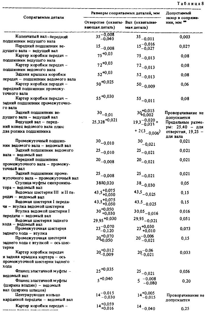
The dimensions of the main mating parts and the limits of permissible wear are shown in Table 8.