
Remove plug 11 (see fig. 60) clutch release drive, and from the guide sleeve of the front cover of the gearbox - clutch 1 complete with bearing and connecting spring. Remove the clutch housing with gasket and front cover 56 (see fig. 66) gearboxes together with an oil seal 1 and a spring washer installed between cover 56 and bearing 2. Unscrew the reversing light switch. Then the drive 38 of the speedometer with the gasket is removed. Having unscrewed the bolt of fastening of the shift fork of III and IV gears, by moving the forks, two gears are switched on simultaneously. This prevents the shafts from turning and allows subsequent disassembly operations.
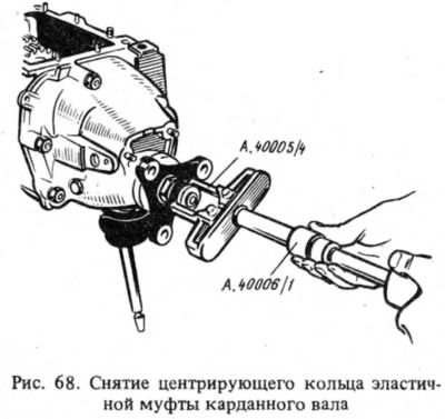
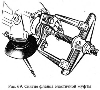
Remove the retaining ring 32 from the end of the driven shaft, then, having unbent the lock washer, unscrew the nut 30 of the flexible coupling flange a few turns to move the centering ring 33, and tighten the nut again. Ejector А.40006/1 (pic. 68) with puller A.40005 / 4 remove the centering ring and seal 31 from the end of the driven shaft (see fig. 66) centering ring of the elastic coupling, unscrew the nut 30 and remove the flange of the elastic coupling with a puller A.40005/3/9B/9C (pic. 69).
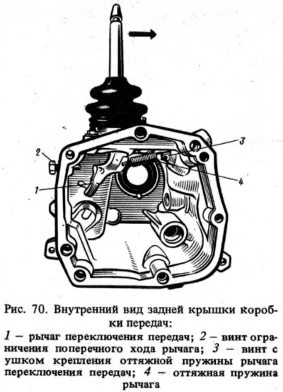
After that, remove the rear cover of the gearbox by unscrewing the screw 2 (pic. 70) limiting the lateral travel of the lever and moving the shift lever in the direction of the arrow to free it from the shift rods.
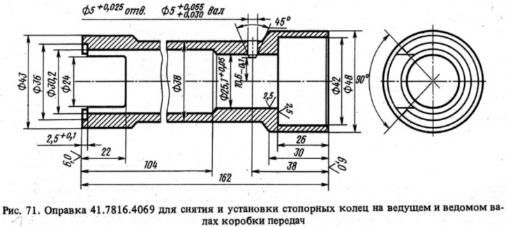
Remove: from the driven shaft - the rear bearing and the drive gear of the speedometer drive; from the reversing rod - a plug with a distance sleeve; from the axis - an intermediate reverse gear; from the intermediate shaft - the circlip of the reverse drive gear, gear and spring washer; from the driven shaft - the retaining ring of the reverse driven gear, pressing with a mandrel 41.7816.4069 (pic. 71) spring washer to take the load off the retaining ring; reverse driven gear and spring washer.
With the help of curly mandrels (screwdriver type) and rod knockouts, the front and rear bearings of the intermediate shaft are pressed out of the gearbox housing and the latter is removed from the housing.
Remove the cover of the clamps with the gasket, remove the springs and balls of the clamps, and from the crankcase - the stem of the reverse gear fork and the stem of the shift fork of III and IV gears. Having unscrewed the bolt securing the shift fork of I and II gears, remove the stem and the shift fork of I and II gears. Taking out the rods, simultaneously remove three blocking (castle) cracker.
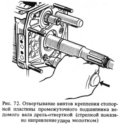
Remove retaining plate (pic. 72) intermediate bearing of the driven shaft and the axis of the intermediate reverse gear. Remove the shaft along with the bearing and synchronizer ring and remove the needle bearing from the front end of the driven shaft. The driven shaft is knocked out of the intermediate bearing, the intermediate bearing is removed and the driven shaft assembly with gears, couplings and synchronizer rings is removed from the crankcase. Then the synchronizer coupling of III and IV gears is removed from the shaft.
When disassembling the drive shaft, the locking and blocking rings and the synchronizer spring are removed from the rear end; install the shaft on the press and, squeezing the spring washer with a mandrel 41.7816.4069, remove the front snap ring, and then the spring washer and bearing.
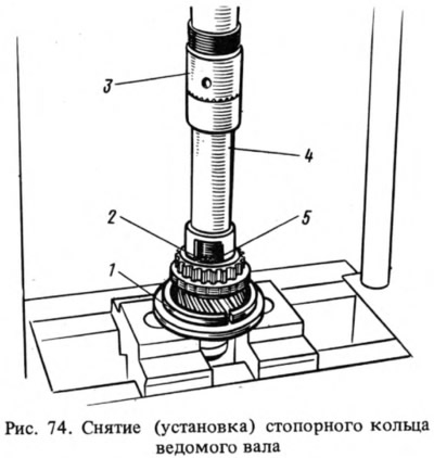
When disassembling the driven shaft (pic. 73) remove from the rear side of the shaft the gear 22 of the 1st gear with the sleeve and the blocking ring 19, the hub with the sliding clutch 17 of switching the 1st and 2nd gears, the gear 11 of the 2nd gear together with the blocking ring 14 of the synchronizer, install the driven shaft with the mandrel 41.7816.4069 (4 - fig. 74) on the press, place support half rings 1 under the gear of the III gear and, pressing the punch 3 through the mandrel on the spring washer 2, remove the retaining ring 5 with tongs, then the spring washer 2, the hub of the sliding clutch of the III and IV gears and the gear of the III gear.
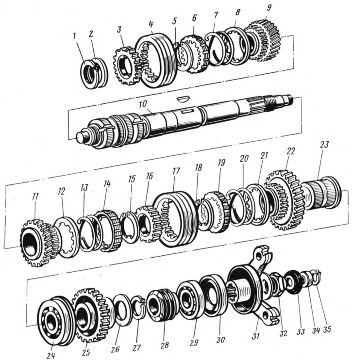
Pic. 73. Details of the driven shaft:
1, 5, 15, 18, 27, 35 - retaining rings; 2, 26 - spring washers; 3, 16 - synchronizer hubs; 4, 17 - synchronizer clutches; 6, 14, 19 - synchronizer blocking rings; 7, 13, 20 - synchronizer springs; 8, 12, 21 - washers; 9, 11, 22 - gears, respectively, III, II and I gears; 10 - driven shaft; 23 - bushing gear 1st gear; 24, 29 - bearings; 25 - reverse gear; 28 - speedometer drive gear; 30 - stuffing box; 31 - flange of an elastic coupling; 32 - nut;
When disassembling the gear lever and the rear cover, remove the cuff 19 (pic. 75), cover 21 of the lever with a clamp, then the retaining ring 14, washer 13, spring 12 and spherical washer 11. Unscrew the flange fastening nuts 16, disconnect the release spring 3 of the lever from the eye of the bolt 1 and remove the lever together with the flange, support and cup 5.
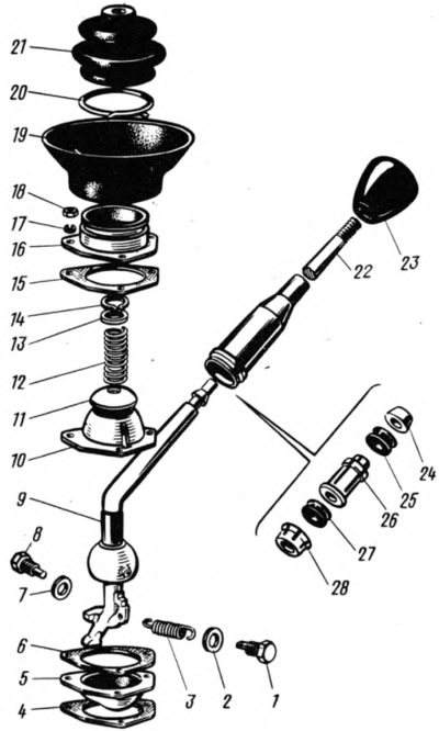
Pic. 75. Gear lever parts:
1 - bolt of the return spring; 2, 7, 13 - washers; 3 - withdrawal spring; 4, 6, 15 - gaskets; 5 - guide cup; 8 - restrictive bolt; 9 - gear lever; - spherical bearing; 11 - spherical washer; 12 - spring; 14 - retaining ring; 16 - flange; 17 - spring washer; 18 - nut; - flange; 20 - collar; 21 - inner cover; 22 - lever rod; 23 - handle; 24 - thrust pad; 25, 27 - elastic bushings; 26 - remote bushing; 28 - locking sleeve.
Note. Since April 1980, clamp 20 has not been installed.
Assemble the gearbox in the reverse order, taking into account the following:
- the spring of the reverse fork rod retainer differs from others in elasticity, it is painted green or has a cadmium coating;
- when connecting the clutch housing to the front cover of the gearbox 56 (see fig. 66) the oil outlet in the front cover must be located at the bottom;
- before installation, cover the working surface of the seals with Litol-24 grease;
- when installing the retaining ring of the reverse gear, use mandrel 41.7816.4069, and when installing bearings and seals, mandrel 41.7853.4028; 41.7853.4032; 41.7853.4039.
Specified mandrels are of the same type. Mandrel 41.7853.4039 has an outer diameter of a punch of 56 mm, from the end of which a centering belt with a diameter of 32.1 mm is made for the gland nozzle.
The mandrel punch 41.7853 has an outer diameter of 60 mm, and a spring-loaded centering rod with a diameter of 19.5 mm is located in the mandrel tube.
Mandrel punch 41.7853.4028 with a diameter of 74 mm.