




Generator G-221
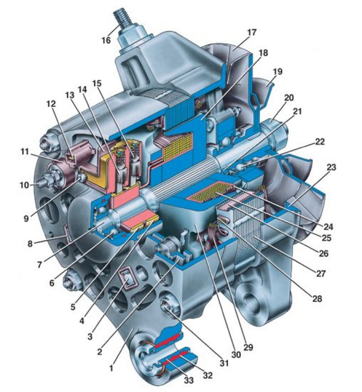
1 – cover from the contact ring side; 2 – rectifier block; 3 – bolt for fastening the rectifier block and stator winding terminals; 4, 5 – slip rings; 6 – rear ball bearing; 7 – rotor shaft; 8 – insulating bushings; 9 – brush holder mounting screw; 10 – positive contact bolt (terminal "30"); 11 – insulating sleeve of contact bolt; 12 – plug of the central terminal of the stator winding; 13 – brush holder; 14 – negative brush; 15 – positive brush; 16 – stud for fastening the generator to the tension bar; 17 – pulley impeller; 18 – rotor pole tip on the drive side; 19 – generator drive pulley; 20 – pulley mounting nut; 21 – distance ring; 22 – front ball bearing; 23 – drive side cover; 24 – rotor winding frame; 25 – rotor winding; 26 – stator slot insulation; 27 – stator; 28 – stator winding wedge; 29 – stator winding; 30 – rotor pole piece from the slip ring side; 31 – tension bolt; 32 – buffer bushing; 33 – bushing
Generator System Wiring Diagram
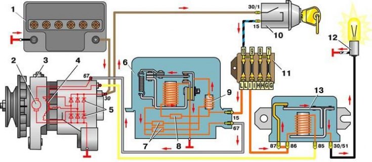
1 – battery; 2 – generator rotor winding; 3 – generator; 4 – generator stator winding; 5 – generator rectifier block; 6 – voltage regulator; 7 – additional resistors; 8 – temperature compensating resistor; 9 – throttle; 10 – ignition switch; 11 – fuse box; 12 – charge indicator lamp; 13 – charge indicator lamp relay
| Nominal voltage | At 12 |
| Direction of rotation | right (from the drive side) |
| Maximum output current at 14 V and rotor speed of 5000 min⁻¹, A | 42 |
| Maximum rotor speed, min⁻¹ | 13000 |
| Engine-generator gear ratio | 1: 2,04 |
On VAZ-2101, -2102 cars and their modifications, a three-phase alternating current generator of the G-221 type was used (see fig. Generator G-221) with a built-in rectifier. Until the mid-80s, the "negative" valves (diodes) of the rectifier were pressed into the cover 1, and the "positive" ones - into a separate plate attached to the cover.
Since the mid-80s, all valves of G-221 generators are located in a non-separable rectifier block 2, consisting of two plates. In case of damage to the valves, the block is replaced with a new one.
Regulator 6 (see fig. Generator system connection diagram) maintains the generator voltage at a level of 13.2–14.5. The generator's serviceability is checked using the control lamp 12 in the instrument cluster and relay 13.
When the ignition is turned on, when the engine (and therefore the generator) does not work yet, current from the battery flows through the relay contacts, and the lamp lights up. After starting the engine and when the car is moving, the lamp should go out, since under the action of the rectified phase voltage of the generator, the relay anchor should be attracted to the core and open the relay contacts.