
- Rated voltage, V, — 12
- Direction of rotation - Right (drive side)
- Maximum output current at 14 V and rotor speed 5000 min-1, A - 42
- Maximum rotor speed, min-1 — 13000
- Gear ratio engine-generator - 1: 2.04
The section of the generator is given in fig. 7-4, and the electrical connection diagram of the generator system in fig. 7-5.
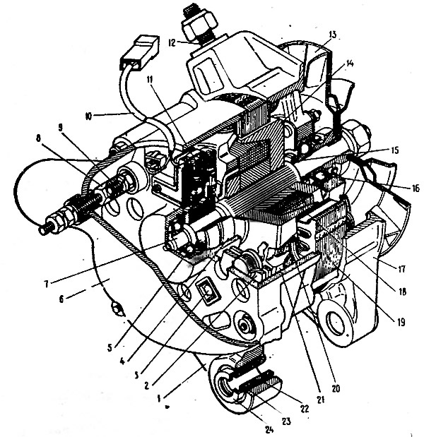
Pic. 7-4. Generator G-221: 1 - cover from the side of slip rings; 2 - rectifier unit, 3 - rectifier unit fastening screw; 4 - contact ring; 5 - rear ball bearing; 6 - protective cover: 7 - rotor shaft, 8 - contact bolt extension; 9 - contact bolt; 10 - bundle of wires; 11 - brush holder with brushes; 12 - stud fastening the generator to the tension bar; 13 - a pulley with a fan; 14 - pole tip of the rotor, 15 - sleeve; 16 - front ball bearing; 17 - cover on the drive side; 18 - rotor winding, 19 - stator; 20 - stator winding; 21 - pole tip of the rotor; 22 - buffer sleeve; 23 - sleeve; 24 - clamping sleeve
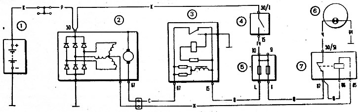
Pic. 7-5. Generator system wiring diagram: 1 - battery; 2 - generator; 3 - voltage regulator; 4 - ignition switch; 5 - fuse box; 6 - charge control lamp; 7 - charge control lamp relay