
Details of the front driveshaft
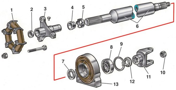
1 - elastic coupling; 2 - centering sleeve; 3 – flexible coupling flange; 4 - stuffing box; 5 – stuffing box holder; 6 - cardan shaft; 7 - dust deflector; 8 - bearing; 9 - retaining ring; 10 - nut; 11 - fork cardan joint; 12 - dust deflector; 13 - elastic support
Assembling the universal joint
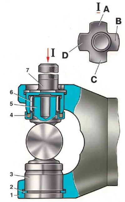
1 - fork cardan joint; 3 - bearing housing; 4 - stuffing box; 5 - spike of the cross; 6 - bearing needle; 7 - caliber 41.8734.4092; A, B, C, D - probe petals having a thickness of 1.53; 1.56; 1.59; 1.62
1. Assemble cardan shafts in the reverse order of disassembly, taking into account the following instructions:
- apply grease FIOL-1 to splined joints;
- when connecting the parts, align the marks made on the detachable parts before disassembly;
- after assembling the spline connection, pressing the stuffing box by 0.3–0.5 mm with an axial load, crimp the clip on the groove of the fork;
- Tighten the front propeller shaft yoke nut with a torque wrench and caulk.
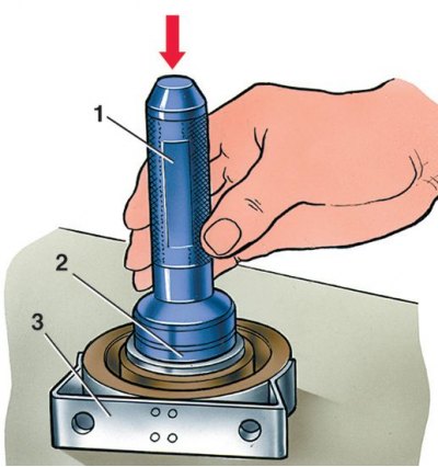
2. When assembling the intermediate support, press the bearing with a mandrel (1 - mandrel A.70045, 2 - bearing, 3 - elastic support) and install a snap ring in the groove of the support.
3. Put on the rear end of the front propeller shaft dust deflector 7 (see fig. Details of the front driveshaft).
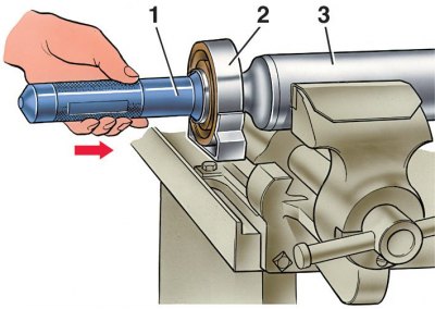
4. mandrel (1 - mandrel A.74035, 2 - elastic support; 3 – a back part of a forward cardan shaft) press the support with the bearing and put on the second dust deflector 12 (see fig. Details of the front driveshaft), press the yoke 11 of the front propeller shaft onto the shaft and fix it with a nut, as indicated above.
5. Assemble the cardan joint in the following order. After removing the old thickened grease, fill the cavities in the spikes of the cross and lubricate the inner surface of the bearing housings with FIOL-2U grease (0.4–0.6 g per bearing). Lubricate the spikes of the cross with a thin layer so that an air cushion does not form during assembly. Insert the spikes of the cross into the fork.
6. Put the bearing housings with needles on the spikes of the cross and press them into the holes of the fork with a force of 7840 N (800 kgf). Install the retaining rings in the grooves of the fork in their original places, according to the marks. Then check the axial free play of the spider, which should be 0.01–0.04 mm. If the free play is greater than the specified value, replace one thinner circlip with a thicker one.
7. When replacing parts of the cardan joint, select retaining rings with caliber 41.7834.4092, which has four petals of different thicknesses (1.53mm; 1.56mm; 1.59mm; 1.62 mm). To do this, install the retaining ring 2 (see fig. Assembling the universal joint) 1.56 mm thick.
8. When pressing bearings, when the cross rests against the bearing housing (in this case there are no gaps), use a feeler gauge to determine the distance between the bearing housing and the end face of the annular groove. Depending on the measured distance, taking into account the axial clearance of 0.01–0.04 mm, insert a second circlip of the appropriate thickness.
Attention! Retaining rings come in five sizes of spare parts (by thickness, mm), each of which has a certain color: 1.50 - unpainted; 1.53 - dark brown; 1.56 - blue; 1.59 - black; 1.62 - yellow.
9. After installing the retaining rings, hit the forks with a plastic-headed hammer. Under the impact and elastically compressed glands, the gap between the bottom of the bearing and the retaining ring is knocked out, and gaps appear between the bearing housings and the ends of the cross spikes. After assembly, check the ease of rotation of the forks of the hinges and the balance of the driveline.