
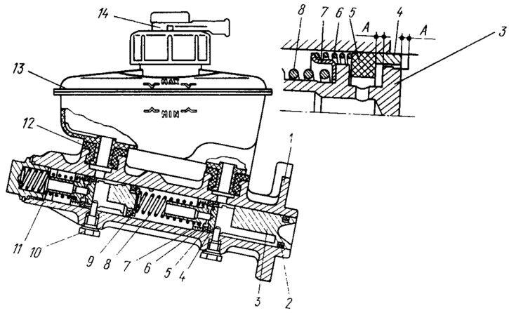
Pic. 79. Master cylinder assembly with tank:
1 - main cylinder body; 2 - low pressure sealing ring; 3 - drive piston «left front - right rear brakes»; 4 - spacer ring; 5 - high pressure sealing ring; 6 - clamping spring of the sealing ring; 7 - spring plate; 8 - piston return spring; 9 - washer; 10 - locking screw; 11 - drive piston «right front - left rear brakes»; 12 - connecting sleeve; 13 - tank; 14 - brake fluid emergency level sensor.
The front floating piston 11 has a similar design, front seal and restriction. Only the rear part of the piston is sealed with a high pressure ring, which is pressed against the end of the piston by a spring 8 through a washer 9. The high pressure sealing rings are interchangeable with the rear brake wheel cylinder rings with a diameter of 20.64 mm.
Tank 13 is attached to the main cylinder with the help of two rubber connecting bushings 12. There are two marks on the body of the tank, made of translucent plastic: «min» and «Max», which controls the level of liquid in the tank. The tank is divided by a partition into two working cavities, which communicate with the working cavities of the main cylinder through the tank fittings and connecting sleeves 12.
In the center of the tank there is a guide cylinder that runs from the filler neck to the bottom of the tank. Two slots are made in the upper part of the cylinder, through which the cavity of the cylinder guide communicates with two working cavities of the tank. Therefore, if fluid leaks from one cavity of the reservoir to another, there is enough fluid left for the normal operation of the brake circuit.
A cap is screwed onto the neck of the tank, which fastens the emergency liquid level sensor to the tank. It consists of base 3 (pic. 80) and housing 2 sensors made of plastic. The sensor body is put on the cylindrical belt of the base and, together with it and the reflector 6, is pressed by the cover 5 to the end of the filler neck. The gap between the sensor body and the base is sealed with ring 4. To fix the cover on the upper part of the base, there are two elastic tabs that snap into place when the cover is completely wrapped. Two fixed contacts 10 with terminals are riveted to the sensor body, on which the wire ends are put on. A pusher 7 passes through the opening of the base 3, at the upper end of which a movable contact 11 is rigidly fixed. At the lower end of the pusher, a polypropylene float 9 is attached through a plastic connecting sleeve 8. From above, the cavity of the sensor contacts is closed with a protective plastic cap 1.
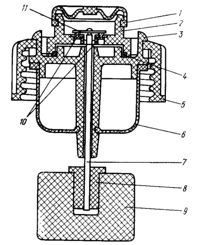
Pic. 80. Emergency brake fluid level sensor:
1 - protective cap; 2 - sensor housing; 3 - sensor base; 4 - sealing ring; 5 - tank cover; 6 - reflector; 7 - pusher; 8 - bushing; 9 - float; 10 - fixed contact; 11 - moving contact.
When the system is released, pistons 11 and 3 (see fig. 79) under the action of the return spring 8, they are pressed to the extreme position and rest against the locking screws 10. In this case, the spacer rings 4, resting against the screws 10, remove the sealing rings 5 from the end grooves of the pistons. As a result, compensation gaps A are formed, through which the working cavities of the main cylinder communicate with the reservoir.
When braking, the vacuum booster rod moves the piston 3. The spacer ring 4 moves away from the locking screw and the sealing ring 5 is pressed by the spring 6 against the end of the groove. The compensation gap is blocked and the cavities of the main cylinder and the reservoir are separated. Therefore, with further movement of the piston 3 in the working cavity of the drive «left front - right rear brakes» fluid pressure is created, which is transmitted through pipelines and hoses to the wheel cylinders of the wheel brake mechanisms. It also affects the floating piston 11, which, while moving, creates pressure in the drive «right front - left rear brakes». Increasing fluid pressure in the working cavities of the cylinder expands the high-pressure rings and they are more strongly pressed against the walls of the cylinder and against the end of the grooves, which improves the sealing of the pistons in the master cylinder.